Asus MAXIMUS III GENE User Manual - Page 28
Onboard LEDs - memory
 |
UPC - 610839173013
View all Asus MAXIMUS III GENE manuals
Add to My Manuals
Save this manual to your list of manuals |
Page 28 highlights
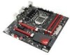
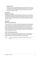
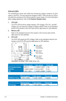
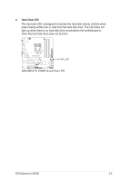
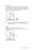
Onboard LEDs The motherboard comes with LEDs that indicate the voltage conditions of CPU, memory, and PCH. You may adjust the voltages in BIOS. There are also an LED for hard disk drive activity and an onboard switch for power status. For more information about voltage adjustment, refer to 3.3 Extreme Tweaker menu. 1. CPU LED The CPU LED has three voltage displays: CPU Voltage, CPU PLL, and IMC Voltage; you can select the voltage to display in BIOS. Refer to the illustration below for the location of the CPU LED and the table below for LED definition. 2. Memory LED Refer to the illustration below for the location of the memory LED and the table below for LED definition. 3. PCH LED The PCH LED shows the PCH Voltage. Refer to the illustration below for the location of the PCH LED and the table below for LED definition. CPU Voltage (default) CPU PLL IMC Normal (green) 0.85-1.4 1.60325-2.00075 1.007-1.3515 High (yellow) 1.40625-1.54375 2.014-2.10675 1.36475-1.60325 Crazy (red) 1.55- 2.12- 1.6165- Normal (green) DRAM Bus Voltage 1.3515-1.60325 High (yellow) 1.6165-1.78875 Crazy (red) 1.80200- PCH Voltage Normal (green) 1.007-1.15275 High (yellow) 1.166-1.20575 Crazy (red) 1.219- 2-2 Chapter 2: Hardware information
-
 1
1 -
2
-
3
-
4
-
5
-
6
-
7
-
8
-
9
-
10
-
11
-
12
-
13
-
14
-
15
-
16
-
17
-
18
-
19
-
20
-
21
-
22
-
 23
23 -
 24
24 -
 25
25 -
 26
26 -
 27
27 -
 28
28 -
 29
29 -
 30
30 -
 31
31 -
 32
32 -
 33
33 -
34
-
35
-
36
-
37
-
38
-
39
-
40
-
41
-
42
-
43
-
44
-
45
-
46
-
47
-
48
-
49
-
50
-
51
-
52
-
53
-
54
-
55
-
56
-
57
-
58
-
59
-
60
-
61
-
62
-
63
-
64
-
65
-
66
-
67
-
68
-
69
-
70
-
71
-
72
-
73
-
74
-
75
-
76
-
77
-
78
-
79
-
80
-
81
-
82
-
83
-
84
-
85
-
86
-
87
-
88
-
89
-
90
-
91
-
92
-
93
-
94
-
95
-
96
-
97
-
98
-
99
-
100
-
101
-
102
-
103
-
104
-
105
-
106
-
107
-
108
-
109
-
110
-
111
-
112
-
113
-
114
-
115
-
116
-
117
-
118
-
119
-
120
-
121
-
122
-
123
-
124
-
125
-
126
-
127
-
128
-
129
-
130
-
131
-
132
-
133
-
134
-
135
-
136
-
137
-
138
-
139
-
140
-
141
-
142
-
143
-
144
-
145
-
146
-
147
-
148
-
149
-
150
-
151
-
152
-
153
-
154
-
155
-
156
-
157
-
158
-
159
-
160
-
161
-
162
-
163
-
164
-
165
-
166
-
167
-
168
-
169
-
170
 |
 |
