Asus MAXIMUS III GENE User Manual - Page 88
CPU PLL Voltage [Auto], IMC Voltage [Auto], PCH Voltage [Auto], DRAM Voltage [Auto], DRAM DATA REF
 |
UPC - 610839173013
View all Asus MAXIMUS III GENE manuals
Add to My Manuals
Save this manual to your list of manuals |
Page 88 highlights
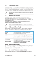
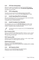
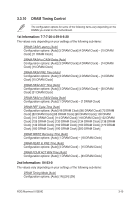
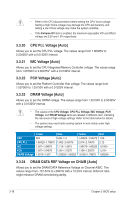
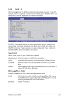
• Refer to the CPU documentation before setting the CPU Vcore voltage. Setting a high VCore voltage may damage the CPU permanently, and setting a low VCore voltage may make the system unstable. • If the Extreme OV item is enabled, the maximum adjustable VID and Offset voltage are 2.2V and 1.9V respectively. 3.3.20 CPU PLL Voltage [Auto] Allows you to set the CPU PLL voltage. The values range from 1.60325V to 2.50425V with a 0.01325V interval. 3.3.21 IMC Voltage [Auto] Allows you to set the CPU Integrated Memory Controller voltage. The values range from 1.00700V to 2.00075V* with a 0.01325V interval. 3.3.22 PCH Voltage [Auto] Allows you to set the Platform Controller Hub voltage. The values range from 1.00700V to 1.35150V with a 0.01325V interval. 3.3.23 DRAM Voltage [Auto] Allows you to set the DRAM voltage. The values range from 1.35150V to 2.50425V with a 0.01325V interval. • The values of the CPU Voltage, CPU PLL Voltage, IMC Voltage, PCH Voltage, and DRAM Voltage items are labeled in different color, indicating the risk levels of high voltage settings. Refer to the table below for details. • The system may need better cooling system to work stably under high voltage settings. CPU CPU PLL IMC PCH DRAM Voltage Green N/A 1.60325-1.78875 1.007-1.09975 1.007-1.04675 1.3515-1.537 Blue 0.85-1.4 1.802-2.00075 1.113-1.3515 1.06-1.15275 1.55025-1.60325 Yellow 1.40625-1.54375 2.014-2.10675 1.36475-1.60325 1.166-1.20575 1.6165-1.78875 Red 1.55- 2.12- 1.6165- 1.219- 1.80200- 3.3.24 DRAM DATA REF Voltage on CHA/B [Auto] Allows you to set the DRAM DATA Reference Voltage on Channel A/B/C. The values range from -157.5mV to +200mV with a 12.5mV interval. Different ratio might enhance DRAM overclocking ability. 3-18 Chapter 3: BIOS setup
-
 1
1 -
2
-
3
-
4
-
5
-
6
-
7
-
8
-
9
-
10
-
11
-
12
-
13
-
14
-
15
-
16
-
17
-
18
-
19
-
20
-
21
-
22
-
23
-
24
-
25
-
26
-
27
-
28
-
29
-
30
-
31
-
32
-
33
-
34
-
35
-
36
-
37
-
38
-
39
-
40
-
41
-
42
-
43
-
44
-
45
-
46
-
47
-
48
-
49
-
50
-
51
-
52
-
53
-
54
-
55
-
56
-
57
-
58
-
59
-
60
-
61
-
62
-
63
-
64
-
65
-
66
-
67
-
68
-
69
-
70
-
71
-
72
-
73
-
74
-
75
-
76
-
77
-
78
-
79
-
80
-
81
-
82
-
 83
83 -
 84
84 -
 85
85 -
 86
86 -
 87
87 -
 88
88 -
 89
89 -
 90
90 -
 91
91 -
 92
92 -
 93
93 -
94
-
95
-
96
-
97
-
98
-
99
-
100
-
101
-
102
-
103
-
104
-
105
-
106
-
107
-
108
-
109
-
110
-
111
-
112
-
113
-
114
-
115
-
116
-
117
-
118
-
119
-
120
-
121
-
122
-
123
-
124
-
125
-
126
-
127
-
128
-
129
-
130
-
131
-
132
-
133
-
134
-
135
-
136
-
137
-
138
-
139
-
140
-
141
-
142
-
143
-
144
-
145
-
146
-
147
-
148
-
149
-
150
-
151
-
152
-
153
-
154
-
155
-
156
-
157
-
158
-
159
-
160
-
161
-
162
-
163
-
164
-
165
-
166
-
167
-
168
-
169
-
170
 |
 |
