Asus MAXIMUS VI EXTREME MAXIMUS VI EXTREME User's Manual - Page 26
Layout contents, Connectors/Jumpers/Buttons and switches/Slots - intel z87
 |
View all Asus MAXIMUS VI EXTREME manuals
Add to My Manuals
Save this manual to your list of manuals |
Page 26 highlights
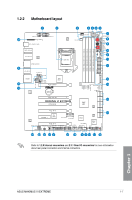
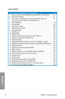
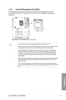
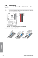
Layout contents Connectors/Jumpers/Buttons and switches/Slots 1. Power connectors (24-pin EATXPWR, 8-pin EATX12V, 4-pin EATX12V) 2. LGA1150 CPU Socket 3. CPU, chassis, and optional fan connectors (4-pin CPU_FAN, 4-pin CPU_OPT, 4-pin OPT_FAN1-3, 4-pin CHA_FAN1-3) 4. DDR3 DIMM slots 5. Q_Code LEDs 6. PCIe x16 Lane switch 7. START (Power-on) button 8. Slow Mode switch 9. RESET button 10. MemOK! button 11. Thermal sensor cable connectors (2-pin OPT_TEMP1-3) 12. USB 3.0 connectors (20-1 pin USB3_12) 13. LN2 Mode header 14. Intel® Z87 Serial ATA 6.0 Gb/s connectors (7-pin SATA6G_1-6 [red]) 15. ASMedia® Serial ATA 6.0 Gb/s connectors (7-pin SATA6G_E12/E34 [red]) 16. BIOS Switch button 17. System panel connector (20-8 pin PANEL) 18. DRCT connector 19. USB 2.0 connectors (10-1 pin USB910; USB1112; USB1314) 20. ROG Extension connector (18-1 pin ROG_EXT) 21. DirectKey button 22. Fastboot switch 23. Front panel audio connector (10-1 pin AAFP) 24. Digital audio connector (4-1 pin SPDIF_OUT) 25. EZ Plug connectors (6-pin EZ_PLUG_1; 4-pin EZ_PLUG_2) 26. mPCIe Combo II slot (MPCIE_COMBO_II) Page 1-43 1-9 1-41 1-10 1-30 1-25 1-22 1-24 1-22 1-23 1-45 1-38 1-27 1-37 1-38 1-24 1-44 1-46 1-40 1-47 1-26 1-25 1-42 1-39 1-45 1-46 Chapter 1 1-8 Chapter 1: Product introduction
-
 1
1 -
2
-
3
-
4
-
5
-
6
-
7
-
8
-
9
-
10
-
11
-
12
-
13
-
14
-
15
-
16
-
17
-
18
-
19
-
20
-
 21
21 -
 22
22 -
 23
23 -
 24
24 -
 25
25 -
 26
26 -
 27
27 -
 28
28 -
 29
29 -
 30
30 -
 31
31 -
32
-
33
-
34
-
35
-
36
-
37
-
38
-
39
-
40
-
41
-
42
-
43
-
44
-
45
-
46
-
47
-
48
-
49
-
50
-
51
-
52
-
53
-
54
-
55
-
56
-
57
-
58
-
59
-
60
-
61
-
62
-
63
-
64
-
65
-
66
-
67
-
68
-
69
-
70
-
71
-
72
-
73
-
74
-
75
-
76
-
77
-
78
-
79
-
80
-
81
-
82
-
83
-
84
-
85
-
86
-
87
-
88
-
89
-
90
-
91
-
92
-
93
-
94
-
95
-
96
-
97
-
98
-
99
-
100
-
101
-
102
-
103
-
104
-
105
-
106
-
107
-
108
-
109
-
110
-
111
-
112
-
113
-
114
-
115
-
116
-
117
-
118
-
119
-
120
-
121
-
122
-
123
-
124
-
125
-
126
-
127
-
128
-
129
-
130
-
131
-
132
-
133
-
134
-
135
-
136
-
137
-
138
-
139
-
140
-
141
-
142
-
143
-
144
-
145
-
146
-
147
-
148
-
149
-
150
-
151
-
152
-
153
-
154
-
155
-
156
-
157
-
158
-
159
-
160
-
161
-
162
-
163
-
164
-
165
-
166
-
167
-
168
-
169
-
170
-
171
-
172
-
173
-
174
-
175
-
176
-
177
-
178
-
179
-
180
-
181
-
182
-
183
-
184
-
185
-
186
-
187
-
188
-
189
-
190
-
191
-
192
-
193
-
194
-
195
-
196
-
197
-
198
-
199
-
200
-
201
-
202
-
203
-
204
-
205
-
206
-
207
-
208
 |
 |