Asus MAXIMUS VI EXTREME MAXIMUS VI EXTREME User's Manual - Page 63
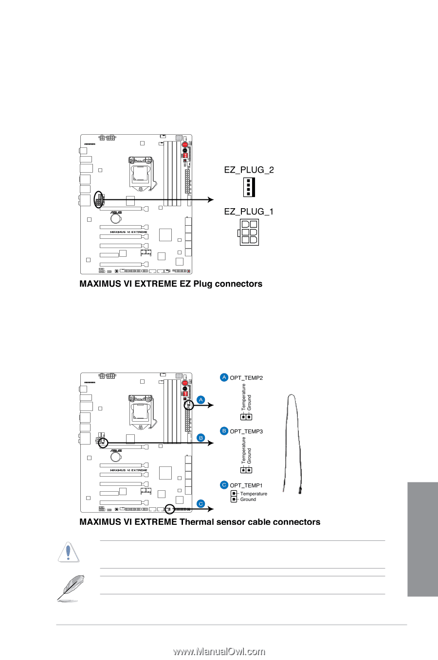
EZ Plug connectors 6-pin EZ_PLUG_1; 4-pin EZ_PLUG_2
 |
View all Asus MAXIMUS VI EXTREME manuals
Add to My Manuals
Save this manual to your list of manuals |
Page 63 highlights
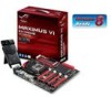
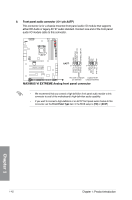
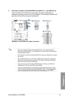
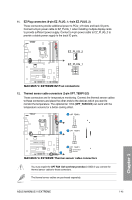
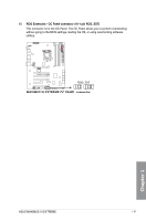
11. EZ Plug connectors (6-pin EZ_PLUG_1; 4-pin EZ_PLUG_2) These connectors provide additional power to PCIe_x16 slots and back IO ports. Connect a 6-pin power cable to EZ_PLUG_1 when installing multiple display cards to provide sufficient power supply. Connect a 4-pin power cable to EZ_PLUG_2 to provide a stable power supply to the back IO ports. 12. Thermal sensor cable connectors (2-pin OPT_TEMP1/2/3) These connectors are for temperature monitoring. Connect the thermal sensor cables to these connectors and place the other ends to the devices which you want to monitor the temperature. The optional fan 1/2/3 (OPT_FAN1/2/3) can work with the temperature sensors for a better cooling effect. Chapter 1 You must enable the OPT FAN 1/2/3 overheat protection in BIOS if you connect the thermal sensor cables to these connectors. The thermal sensor cables are purchased separately. ASUS MAXIMUS VI EXTREME 1-45
-
 1
1 -
2
-
3
-
4
-
5
-
6
-
7
-
8
-
9
-
10
-
11
-
12
-
13
-
14
-
15
-
16
-
17
-
18
-
19
-
20
-
21
-
22
-
23
-
24
-
25
-
26
-
27
-
28
-
29
-
30
-
31
-
32
-
33
-
34
-
35
-
36
-
37
-
38
-
39
-
40
-
41
-
42
-
43
-
44
-
45
-
46
-
47
-
48
-
49
-
50
-
51
-
52
-
53
-
54
-
55
-
56
-
57
-
 58
58 -
 59
59 -
 60
60 -
 61
61 -
 62
62 -
 63
63 -
 64
64 -
 65
65 -
 66
66 -
 67
67 -
 68
68 -
69
-
70
-
71
-
72
-
73
-
74
-
75
-
76
-
77
-
78
-
79
-
80
-
81
-
82
-
83
-
84
-
85
-
86
-
87
-
88
-
89
-
90
-
91
-
92
-
93
-
94
-
95
-
96
-
97
-
98
-
99
-
100
-
101
-
102
-
103
-
104
-
105
-
106
-
107
-
108
-
109
-
110
-
111
-
112
-
113
-
114
-
115
-
116
-
117
-
118
-
119
-
120
-
121
-
122
-
123
-
124
-
125
-
126
-
127
-
128
-
129
-
130
-
131
-
132
-
133
-
134
-
135
-
136
-
137
-
138
-
139
-
140
-
141
-
142
-
143
-
144
-
145
-
146
-
147
-
148
-
149
-
150
-
151
-
152
-
153
-
154
-
155
-
156
-
157
-
158
-
159
-
160
-
161
-
162
-
163
-
164
-
165
-
166
-
167
-
168
-
169
-
170
-
171
-
172
-
173
-
174
-
175
-
176
-
177
-
178
-
179
-
180
-
181
-
182
-
183
-
184
-
185
-
186
-
187
-
188
-
189
-
190
-
191
-
192
-
193
-
194
-
195
-
196
-
197
-
198
-
199
-
200
-
201
-
202
-
203
-
204
-
205
-
206
-
207
-
208
 |
 |