Asus NRL-LS NRL-LS User Manual - Page 42
Hardware information, Clear RTC RAM CLRTC1, Keyboard Power setting 3-pin J4
 |
View all Asus NRL-LS manuals
Add to My Manuals
Save this manual to your list of manuals |
Page 42 highlights
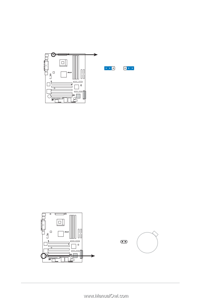
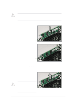
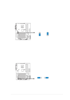
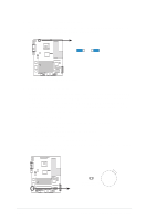
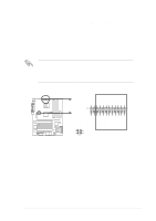
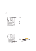
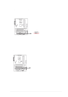
3. Keyboard Power setting (3-pin J4) This jumper is set by default, pins [2-3], to enable keyboard power up. Reset to pins [1-2] to disable keyboard power up. ® NRL-LS J4 12 23 +5V +5VSB (Default) NRL-LS Keyboard Power Setting 4. Clear RTC RAM (CLRTC1) These solder pads allow you to clear the Real Time Clock (RTC) RAM in CMOS. You can clear the CMOS memory of date, time, and system setup parameters by erasing the CMOS RTC RAM data. The RAM data in CMOS, that include system setup information such as system passwords, is powered by the onboard button cell battery. To erase the RTC RAM: 1. Turn OFF the computer and unplug the power cord. 2. Remove the battery. 3. Short the solder pads for about 5 seconds. 4. Re-install the battery. 5. Plug the power cord and turn ON the computer. 6. Hold down the key during the boot process and enter BIOS setup to re-enter data. ® NRL-LS NRL-LS Clear RTC RAM 2-16 CLRTC1 CR2032 3V Lithium Cell CMOS Power Short solder points to Clear CMOS Chapter 2: Hardware information
-
 1
1 -
2
-
3
-
4
-
5
-
6
-
7
-
8
-
9
-
10
-
11
-
12
-
13
-
14
-
15
-
16
-
17
-
18
-
19
-
20
-
21
-
22
-
23
-
24
-
25
-
26
-
27
-
28
-
29
-
30
-
31
-
32
-
33
-
34
-
35
-
36
-
 37
37 -
 38
38 -
 39
39 -
 40
40 -
 41
41 -
 42
42 -
 43
43 -
 44
44 -
 45
45 -
 46
46 -
 47
47 -
48
-
49
-
50
-
51
-
52
-
53
-
54
-
55
-
56
-
57
-
58
-
59
-
60
-
61
-
62
-
63
-
64
-
65
-
66
-
67
-
68
-
69
-
70
-
71
-
72
-
73
-
74
-
75
-
76
-
77
-
78
-
79
-
80
-
81
-
82
-
83
-
84
-
85
-
86
-
87
-
88
-
89
-
90
-
91
-
92
-
93
-
94
-
95
-
96
-
97
-
98
-
99
-
100
-
101
-
102
-
103
-
104
-
105
-
106
-
107
-
108
-
109
-
110
-
111
-
112
-
113
-
114
-
115
-
116
-
117
-
118
-
119
-
120
 |
 |