Asus P I-P55T2P4S User Manual - Page 30
IDE activity LED JP20
 |
View all Asus P I-P55T2P4S manuals
Add to My Manuals
Save this manual to your list of manuals |
Page 30 highlights
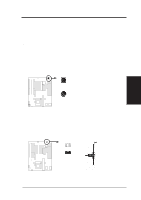
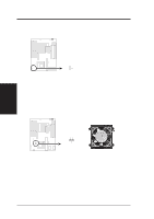
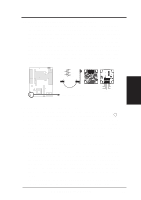
III. INSTALLATION 14. IDE activity LED (JP20) This connector connects to the hard disk activity indicator light on the case. JP21 + IDE (Hard Drive) LED 15. CPU cooling fan connector (JP13) This connector supports a CPU cooling fan of 500mAMP (6WATT) or less. Depending on the fan manufacturer, the wiring may be different. The red wire should be positive, while the black should be ground. Connect the fan to the board taking into consideration the polarity of the connector. WARNING: Damage may occur to the motherboard and/or the CPU fan if these pins are incorrectly used. GND JP2 +12V CPU Fan Power III. INSTALLATION (Connectors) 24 P/I-P55T2P4 User's Manual
-
 1
1 -
2
-
3
-
4
-
5
-
6
-
7
-
8
-
9
-
10
-
11
-
12
-
13
-
14
-
15
-
16
-
17
-
18
-
19
-
20
-
21
-
22
-
23
-
24
-
 25
25 -
 26
26 -
 27
27 -
 28
28 -
 29
29 -
 30
30 -
 31
31 -
 32
32 -
 33
33 -
 34
34 -
 35
35 -
36
-
37
-
38
-
39
-
40
-
41
-
42
-
43
-
44
-
45
-
46
-
47
-
48
-
49
-
50
-
51
-
52
-
53
-
54
-
55
-
56
-
57
-
58
-
59
-
60
 |
 |

P/I-P55T2P4 User's Manual
24
III. INSTALLATION
(Connectors)
III.
INSTALLATION
14. IDE activity LED (JP20)
This connector connects to the hard disk activity indicator light on the
case.
IDE (Hard Drive) LED
JP21
+
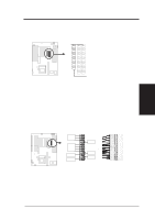
15. CPU cooling fan connector (JP13)
This connector supports a CPU cooling fan of 500mAMP (6WATT) or
less.
Depending on the fan manufacturer, the wiring may be different.
The red wire should be positive, while the black should be ground.
Connect the fan to the board taking into consideration the polarity of
the connector.
WARNING:
Damage may occur to the motherboard and/or the
CPU fan if these pins are incorrectly used.
GND
CPU Fan Power
+12V
JP2