Asus P I-P55T2P4S User Manual - Page 31
Final Power Connection Procedures
 |
View all Asus P I-P55T2P4S manuals
Add to My Manuals
Save this manual to your list of manuals |
Page 31 highlights
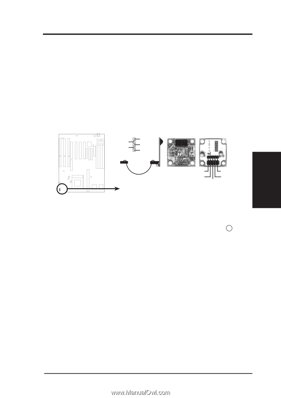
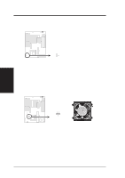
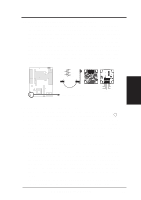
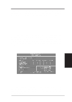
III. INSTALLATION 16. IrDA-compliant infrared module connector (IR) This connector supports the optional wireless transmitting and receiving infrared module. This module mounts to a small opening on system cases that support this feature. You must also configure the setting through BIOS setup on page 37 to select whether UART2 is directed for use with COM2 or IrDA. Use the five pins (as defined by Intel) as shown on the Back View and connect a ribbon cable from the module to the motherboard according to the pin definitions. The ribbon cable that may be supplied may either have five or ten pins (for other standards). If using a ten-pin ribbon cable, use only the top five row of the ribbon cable plug. NC GND +5V IRRX IRTX Front View Back View Infrared Module Connector IRTX +5V GND NC IRRX III. INSTALLATION (Connectors) Final Power Connection Procedures 1. After all jumpers and connections are made, close the system case cover. 2. Make sure that all switches are in the off position as marked by . 3. Connect the power supply cord into the power supply located on the back of your system case as instructed by your system user's manual. 4. Connect the power cord into an power outlet that is equipped by a surge protector. 5. You may then turn on your devices in the following order: a. Your monitor b. External SCSI devices (starting with the last device on the chain) c. Your system power 6. The power LED on the front panel of the system case will light and the monitor LED as well. The system will then run power-on tests. While the tests are running, additional messages will appear on the screen. If you do not see anything within 30 seconds from the time you turn on the power, the system may have failed a power-on test. Recheck your jumper settings and connections or call your authorized dealer for assistance. 7. During power-on, hold down the key to enter BIOS setup. Follow the next section "BIOS SOFTWARE" for instructions. P/I-P55T2P4 User's Manual 25
-
 1
1 -
2
-
3
-
4
-
5
-
6
-
7
-
8
-
9
-
10
-
11
-
12
-
13
-
14
-
15
-
16
-
17
-
18
-
19
-
20
-
21
-
22
-
23
-
24
-
25
-
 26
26 -
 27
27 -
 28
28 -
 29
29 -
 30
30 -
 31
31 -
 32
32 -
 33
33 -
 34
34 -
 35
35 -
 36
36 -
37
-
38
-
39
-
40
-
41
-
42
-
43
-
44
-
45
-
46
-
47
-
48
-
49
-
50
-
51
-
52
-
53
-
54
-
55
-
56
-
57
-
58
-
59
-
60
 |
 |