Asus P3V4X P3V4X User Manual - Page 23
Central Processing Unit CPU
 |
View all Asus P3V4X manuals
Add to My Manuals
Save this manual to your list of manuals |
Page 23 highlights
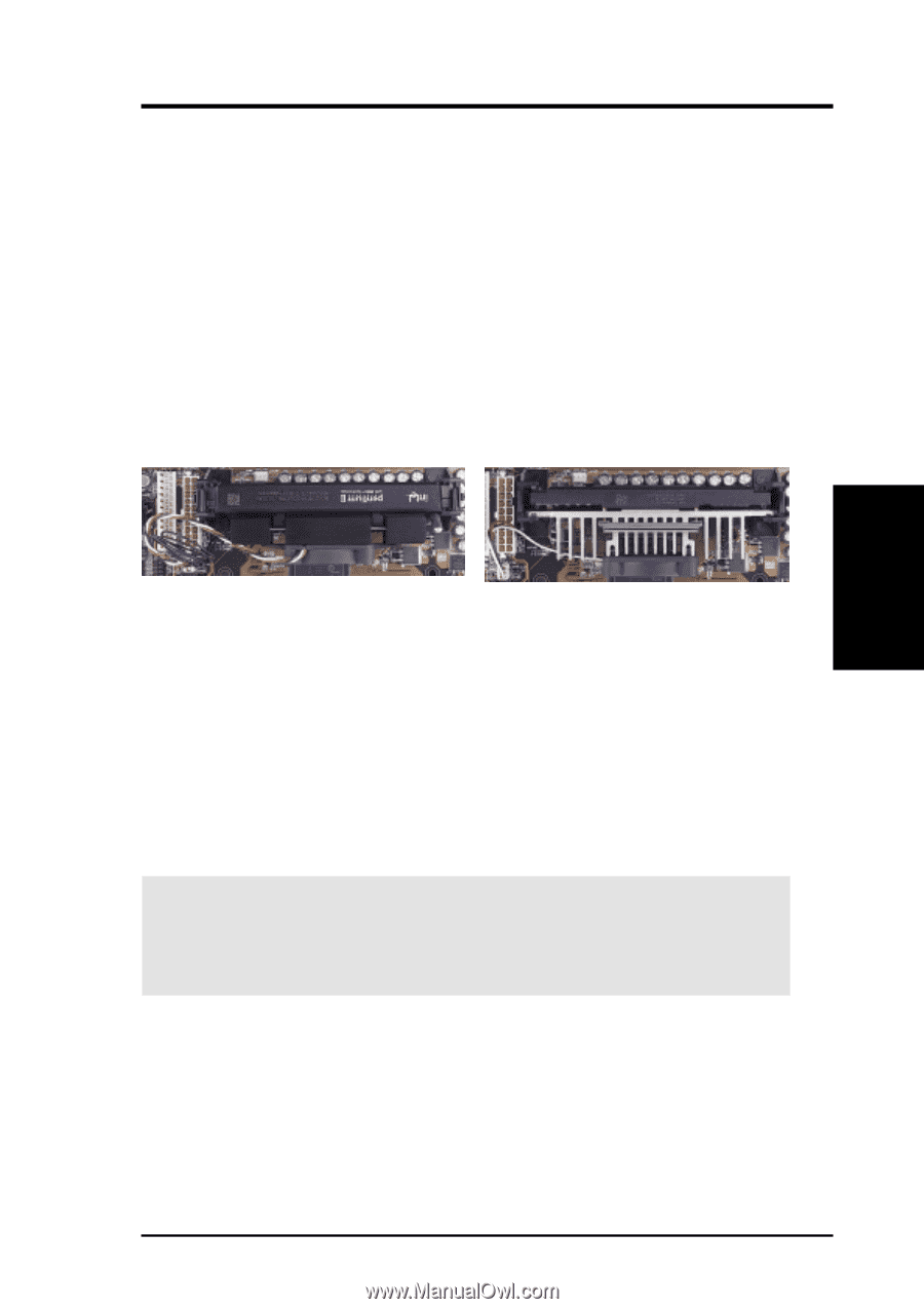
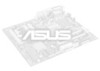
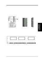
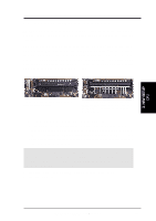
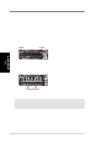
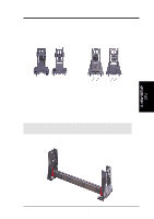
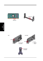
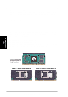
3. H/W SETUP CPU 3. HARDWARE SETUP 3.6 Central Processing Unit (CPU) NOTE: The following pictures are provided for reference purposes only. The appearance of your retention mechanism and fan may be different from the following examples. Your motherboard provides a Slot 1 connector for a Pentium® III processor packaged in a Single Edge Contact Cartridge 2 (SECC2), a Pentium® II processor packaged in SECC, or a Celeron™ processor packaged in a Single Edge Processor Package (SEPP). An ASUS S370 Series CPU card can allow Socket 370 processors to be used on ASUS motherboards with a Slot 1 connector. (See 7.1 ASUS S370 Series CPU Cards for instructions on using this card.) Pentium II processor packaged in an SECC with heatsink and fan (top view) Pentium III (in an SECC2) with heatsink and fan NOTE: The SEPP fan (for Celeron processors) is similar to SECC2 fan except that the clamping design is different. 3.6.1 Quick CPU Installation Procedure 1. Attach the heatsink to the processor with thermal grease and retention clip. The recommended heatsinks (see section on recommended heatsinks for Pentium III / II processors for more information) for the boxed Pentium III / II and Celeron processors are those with three-pin fans that can be connected to the fan connectors on the motherboard. WARNING! Be sure that there is sufficient air circulation across the processor's heatsink by regularly checking that your CPU fan is working. Without sufficient circulation, the processor could overheat and damage both the processor and the motherboard. You may install an auxiliary chassis fan, if necessary. 2. Install the Universal Retention Mechanism onto the motherboard. 3. Insert the processor. ASUS P3V4X User's Manual 23
-
 1
1 -
2
-
3
-
4
-
5
-
6
-
7
-
8
-
9
-
10
-
11
-
12
-
13
-
14
-
15
-
16
-
17
-
 18
18 -
 19
19 -
 20
20 -
 21
21 -
 22
22 -
 23
23 -
 24
24 -
 25
25 -
 26
26 -
 27
27 -
 28
28 -
29
-
30
-
31
-
32
-
33
-
34
-
35
-
36
-
37
-
38
-
39
-
40
-
41
-
42
-
43
-
44
-
45
-
46
-
47
-
48
-
49
-
50
-
51
-
52
-
53
-
54
-
55
-
56
-
57
-
58
-
59
-
60
-
61
-
62
-
63
-
64
-
65
-
66
-
67
-
68
-
69
-
70
-
71
-
72
-
73
-
74
-
75
-
76
-
77
-
78
-
79
-
80
-
81
-
82
-
83
-
84
-
85
-
86
-
87
-
88
-
89
-
90
-
91
-
92
-
93
-
94
-
95
-
96
 |
 |