Asus P3V4X P3V4X User Manual - Page 40
ATX Power Switch / Soft-Off Switch Lead 2-pin PWR.SW - bios reset
 |
View all Asus P3V4X manuals
Add to My Manuals
Save this manual to your list of manuals |
Page 40 highlights
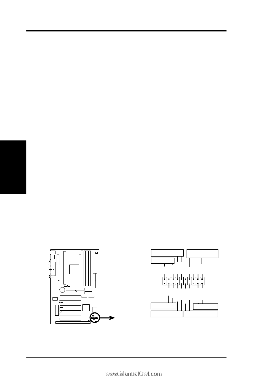
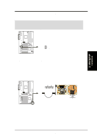
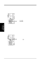
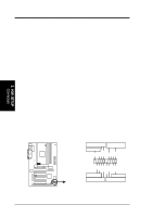
3. H/W SETUP Connectors 3. HARDWARE SETUP 17. System Power LED Lead (3-1 pin PWR.LED) This 3-1 pin connector connects to the system power LED, which lights when the system is powered on and blinks when it is in sleep or soft-off mode. 18. Keyboard Lock Switch Lead (2-pin KEYLOCK) This 2-pin connector connects to the case-mounted key switch to allow keyboard locking. NOTE: When the keyboard is locked, the mouse can still be used. 19. System Warning Speaker Connector (4-pin SPEAKER) This 4-pin connector connects to the case-mounted speaker. 20. System Message LED Lead (2-pin MSG.LED) This indicates whether a message has been received from a fax/modem. The LED will remain lit when there is no signal and blink when there is data received. This function requires an ACPI OS and driver support. 21. System Management Interrupt Lead (2-pin SMI) This allows the user to manually place the system into a suspend mode or "Green" mode where system activity will be instantly decreased to save electricity and expand the life of certain components when the system is not in use. This 2-pin connector connects to the case-mounted suspend switch. 22. ATX Power Switch / Soft-Off Switch Lead (2-pin PWR.SW) The system power is controlled by a momentary switch connected to this lead. Pushing the button once will switch the system between ON and SLEEP or ON and SOFT OFF, depending on your BIOS or OS setting. Pushing the switch while in the ON mode for more than 4 seconds will turn the system off. The system power LED shows the status of the system's power. 23. Reset Switch Lead (2-pin RESET) This 2-pin connector connects to the case-mounted reset switch for rebooting your computer without having to turn off your power switch. This is a preferred method of rebooting to prolong the life of the system's power supply. Keyboard Lock Power LED Speaker Connector +5 V PLED Keylock Ground +5V Ground Ground SPKR P3V4X R +5 V MLED ExtSMI# Ground PWR_SW Ground ResetCon Ground Message LED Reset SW SMI Lead ATX Power Switch* * Requires an ATX power supply. P3V4X System Panel Connections 40 ASUS P3V4X User's Manual
-
 1
1 -
2
-
3
-
4
-
5
-
6
-
7
-
8
-
9
-
10
-
11
-
12
-
13
-
14
-
15
-
16
-
17
-
18
-
19
-
20
-
21
-
22
-
23
-
24
-
25
-
26
-
27
-
28
-
29
-
30
-
31
-
32
-
33
-
34
-
 35
35 -
 36
36 -
 37
37 -
 38
38 -
 39
39 -
 40
40 -
 41
41 -
 42
42 -
 43
43 -
 44
44 -
 45
45 -
46
-
47
-
48
-
49
-
50
-
51
-
52
-
53
-
54
-
55
-
56
-
57
-
58
-
59
-
60
-
61
-
62
-
63
-
64
-
65
-
66
-
67
-
68
-
69
-
70
-
71
-
72
-
73
-
74
-
75
-
76
-
77
-
78
-
79
-
80
-
81
-
82
-
83
-
84
-
85
-
86
-
87
-
88
-
89
-
90
-
91
-
92
-
93
-
94
-
95
-
96
 |
 |