Asus P3V4X P3V4X User Manual - Page 35
ASUS P3V4X User's Manual, IDE Device Activity LED 2-pin IDELED, Wake-On-Ring Connector 2-pin WOR,
 |
View all Asus P3V4X manuals
Add to My Manuals
Save this manual to your list of manuals |
Page 35 highlights
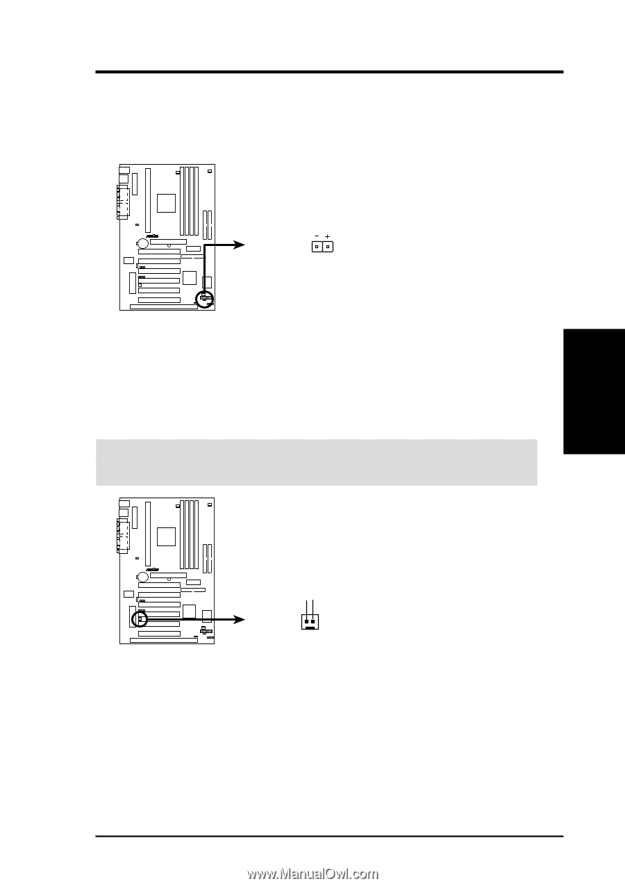
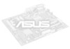
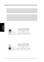
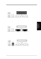
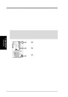
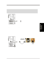
3. H/W SETUP Connectors 3. HARDWARE SETUP 8. IDE Device Activity LED (2-pin IDELED) This connector supplies power to the cabinet's IDE device activity LED. Read and write activity by devices connected to the Primary or Secondary IDE connectors will cause the LED to light up. TIP: If the case-mounted LED does not light, try reversing the 2-pin plug. P3V4X R IDELED P3V4X IDE Activity LED 9. Wake-On-Ring Connector (2-pin WOR) This connector connects to internal modem cards with a Wake-On-Ring output. The connector powers up the system when a ringup packet or signal is received through the internal modem card. NOTE: For external modems, Wake-On-Ring is detected through the COM port. IMPORTANT: This feature requires that the PWR UP On External Modem Act is set to Enabled (see 4.5.1 Power Up Control). P3V4X R WOR PIXRI# Ground 21 P3V4X Wake-On-Ring Connector ASUS P3V4X User's Manual 35
-
 1
1 -
2
-
3
-
4
-
5
-
6
-
7
-
8
-
9
-
10
-
11
-
12
-
13
-
14
-
15
-
16
-
17
-
18
-
19
-
20
-
21
-
22
-
23
-
24
-
25
-
26
-
27
-
28
-
29
-
 30
30 -
 31
31 -
 32
32 -
 33
33 -
 34
34 -
 35
35 -
 36
36 -
 37
37 -
 38
38 -
 39
39 -
 40
40 -
41
-
42
-
43
-
44
-
45
-
46
-
47
-
48
-
49
-
50
-
51
-
52
-
53
-
54
-
55
-
56
-
57
-
58
-
59
-
60
-
61
-
62
-
63
-
64
-
65
-
66
-
67
-
68
-
69
-
70
-
71
-
72
-
73
-
74
-
75
-
76
-
77
-
78
-
79
-
80
-
81
-
82
-
83
-
84
-
85
-
86
-
87
-
88
-
89
-
90
-
91
-
92
-
93
-
94
-
95
-
96
 |
 |