Asus P4G8X P4G8X User Manual - Page 53
ASUS P4G8X series motherboard user guide, IEEE 1394 connectors 10-1 pin IE1394_1, IE1394_2, Infrared
 |
View all Asus P4G8X manuals
Add to My Manuals
Save this manual to your list of manuals |
Page 53 highlights
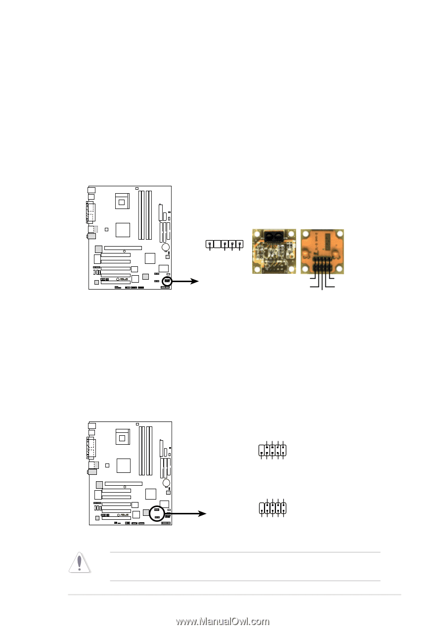
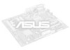
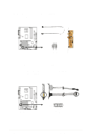
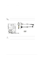
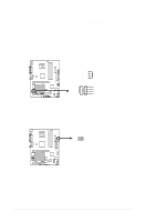
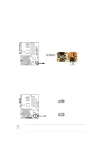
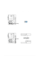
14. Infrared module connector (5-1 pin IR_CON) This connector supports an optional wireless transmitting and receiving infrared module. This module mounts to a small opening on system chassis that support this feature. You must also configure the UART2 Use As parameter in BIOS to set UART2 for use with IR. See section "4.4.2 I/O Device Configuration" for details. Use the five pins as shown in Back View and connect a ribbon cable from the module to the motherboard SIR connector according to the pin definitions. IR_CON 1 Front View Back View +5V IRRX GND IRTX P4G8X ® P4G8X Infrared Module Connector IRTX GND IRRX +5V (NC) 15. IEEE 1394 connectors (10-1 pin IE1394_1, IE1394_2) (on 1394 models only) These connectors are for the bundled 10-to-6-pin 1394 serial connector cables that connect to the 1394 module. Attach the 10-1 pin cable plugs to these connectors, and the 6-pin cable plugs to the 1394 module. You may also connect a 1394-compliant internal hard disk to these connectors. +12V TPB1+ GND TPA1+ 1 IE1394_2 GND +12V +12V TPB0+ TPB1GND GND TPA0+ TPA1- P4G8X ® 1 IE1394_1 GND +12V TPB0GND TPA0- P4G8X IEEE-1394 Connectors NEVER connect a USB cable to any of the IEEE 1394 connectors. Doing so will damage the motherboard! ASUS P4G8X series motherboard user guide 2-27
-
 1
1 -
2
-
3
-
4
-
5
-
6
-
7
-
8
-
9
-
10
-
11
-
12
-
13
-
14
-
15
-
16
-
17
-
18
-
19
-
20
-
21
-
22
-
23
-
24
-
25
-
26
-
27
-
28
-
29
-
30
-
31
-
32
-
33
-
34
-
35
-
36
-
37
-
38
-
39
-
40
-
41
-
42
-
43
-
44
-
45
-
46
-
47
-
 48
48 -
 49
49 -
 50
50 -
 51
51 -
 52
52 -
 53
53 -
 54
54 -
 55
55 -
 56
56 -
 57
57 -
 58
58 -
59
-
60
-
61
-
62
-
63
-
64
-
65
-
66
-
67
-
68
-
69
-
70
-
71
-
72
-
73
-
74
-
75
-
76
-
77
-
78
-
79
-
80
-
81
-
82
-
83
-
84
-
85
-
86
-
87
-
88
-
89
-
90
-
91
-
92
-
93
-
94
-
95
-
96
-
97
-
98
-
99
-
100
-
101
-
102
-
103
-
104
-
105
-
106
-
107
-
108
-
109
-
110
-
111
-
112
-
113
-
114
-
115
-
116
-
117
-
118
-
119
-
120
-
121
-
122
-
123
-
124
-
125
-
126
-
127
-
128
-
129
-
130
-
131
-
132
-
133
-
134
-
135
-
136
 |
 |