Asus P4PE P4PE User Manual - Page 28
Motherboard layout - socket 478 motherboard
 |
View all Asus P4PE manuals
Add to My Manuals
Save this manual to your list of manuals |
Page 28 highlights
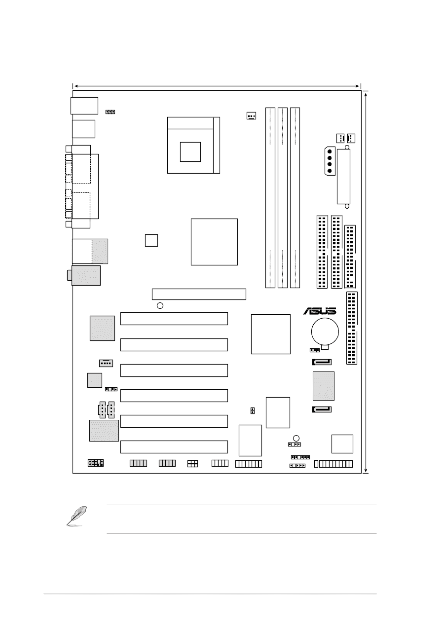
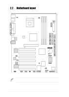
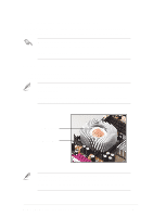
30.5cm (12.0in) 2.2 Motherboard layout PS/2KBMS T: Mouse B: Keyboard USB2.0 T: USB4 B: USB3 COM1 KBPWR1 22.86cm (9.0in) Socket 478 CPU_FAN1 CHA_FAN1 PWR_FAN1 PRI_IDE ATX Power Connector FLOPPY1 EZ_PLUG1 SEC_IDE DDR DIMM1 (64/72 bit, 184-pin module) DDR DIMM2 (64/72 bit, 184-pin module) DDR DIMM3 (64/72 bit, 184-pin module) PARALLEL PORT COM2 USB2.0 Top: T:USB1 B:USB2 RJ-45 ATX12V1 Intel 845PE Memory Controller Hub (MCH) Top:Line In Center:Line Out Below:Mic In BroadCom Gbit/Fast BCM5702/4401 Ethernet Accelerated Graphics Port (AGP) AGP_WARN1 PCI1 P4PE PCI2 01 23 45 Intel I/O Controller Hub (ICH4) ® CR2032 3V Lithium Cell CMOS Power CLRTC1 PROMISE SATA Controller PRI_RAID1 MODEM Audio Codec SPDIF1 PCI3 PCI4 CD1 AUX1 VIA VT6307 Chipset PCI5 BlueMagic PCI Slot IEEE1394_1 IEEE1394_2 FP_AUDIO1 WPCI_USB USB_56 SEC_SATA TRPWR1 ASUS ASIC with Hardware Monitor PRI_SATA Super I/O GAME1 SB_PWR1 CHASSIS1 SMB1 IR1 IDE_LED1 4Mbit Firmware Hub PANEL1 The audio, Serial ATA, IEEE 1394, and LAN features are optional. These components are grayed out in the above motherboard layout. 2-2 Chapter 2: Hardware information
-
 1
1 -
2
-
3
-
4
-
5
-
6
-
7
-
8
-
9
-
10
-
11
-
12
-
13
-
14
-
15
-
16
-
17
-
18
-
19
-
20
-
21
-
22
-
 23
23 -
 24
24 -
 25
25 -
 26
26 -
 27
27 -
 28
28 -
 29
29 -
 30
30 -
 31
31 -
 32
32 -
 33
33 -
34
-
35
-
36
-
37
-
38
-
39
-
40
-
41
-
42
-
43
-
44
-
45
-
46
-
47
-
48
-
49
-
50
-
51
-
52
-
53
-
54
-
55
-
56
-
57
-
58
-
59
-
60
-
61
-
62
-
63
-
64
-
65
-
66
-
67
-
68
-
69
-
70
-
71
-
72
-
73
-
74
-
75
-
76
-
77
-
78
-
79
-
80
-
81
-
82
-
83
-
84
-
85
-
86
-
87
-
88
-
89
-
90
-
91
-
92
-
93
-
94
-
95
-
96
-
97
-
98
-
99
-
100
-
101
-
102
-
103
-
104
-
105
-
106
-
107
-
108
-
109
-
110
-
111
-
112
-
113
-
114
-
115
-
116
-
117
-
118
-
119
-
120
-
121
-
122
-
123
-
124
-
125
-
126
-
127
-
128
-
129
-
130
-
131
-
132
-
133
-
134
-
135
-
136
-
137
-
138
-
139
-
140
-
141
-
142
 |
 |