Asus P4T-F User Manual - Page 12

P4T-F Motherboard Components - p4t form factor

Page 12 highlights

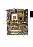
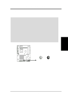
2. FEATURES MB Components 2. FEATURES 2.2 P4T-F Motherboard Components See opposite page for locations. Location Processor Support Socket 423 for Pentium 4 Processors 2 Chipsets Intel 850 Memory Controller Hub (MCH 4 Intel I/O Controller Hub 2 (ICH2 11 2Mbit Firmware Hub (FWH 13 Low Pin Count (LPC) Super Multi-I/O Chipset 16 Main Memory Maximum 1GB support 4 RIMM Sockets 5 Dual Channel PC800/PC600 RDRAM support Switches DSW Frequency Setting 9 Expansion Slots 5 PCI Slots 17 1 Accelerated Graphics Port (AGP Pro) Slot 20 Communictions Network Riser (CNR 15 System I/O 2 IDE Connectors (UltraDMA33/66/100 support 7 1 Floppy Disk Drive Connector 8 1 USB Header (supports 2 USB ports 12 1 Parallel Port Connector Top) 24 1 Serial COM1 Port Connector Bottom) 25 1 Serial COM2 Port Connector Bottom) 23 2 USB Port Connectors 26 1 PS/2 Mouse Connector Top) 27 1 PS/2 Keyboard Connector Bottom) 27 Audio Headphone Connector 18 AC'97 Audio CODEC 19 Microphone 2 Connector 21 1 Game/MIDI Connector Top) 22 1 Line Out Connector Bottom) 22 1 Line In Connector Bottom) 22 1 Line Microphone Connector Bottom) 22 Hardware Monitoring ASUS onboard chipset 10 Power ATX Power Supply Connector 1 ATX 12V Power Supply Connector 3 Special Feature Auxillary Power Connector 6 Onboard LED 14 Form Factor ATX 12 ASUS P4T-F User's Manual

  • 1
  • 2
  • 3
  • 4
  • 5
  • 6
  • 7
  • 8
  • 9
  • 10
  • 11
  • 12
  • 13
  • 14
  • 15
  • 16
  • 17
  • 18
  • 19
  • 20
  • 21
  • 22
  • 23
  • 24
  • 25
  • 26
  • 27
  • 28
  • 29
  • 30
  • 31
  • 32
  • 33
  • 34
  • 35
  • 36
  • 37
  • 38
  • 39
  • 40
  • 41
  • 42
  • 43
  • 44
  • 45
  • 46
  • 47
  • 48
  • 49
  • 50
  • 51
  • 52
  • 53
  • 54
  • 55
  • 56
  • 57
  • 58
  • 59
  • 60
  • 61
  • 62
  • 63
  • 64
  • 65
  • 66
  • 67
  • 68
  • 69
  • 70
  • 71
  • 72
  • 73
  • 74
  • 75
  • 76
  • 77
  • 78
  • 79
  • 80
  • 81
  • 82
  • 83
  • 84
  • 85
  • 86
  • 87
  • 88
  • 89
  • 90
  • 91
  • 92
  • 93
  • 94
  • 95
  • 96

12
ASUS P4T-F User’s Manual
2.
FEATURES
2.2
P4T-F Motherboard Components
See
opposite page for locations.
Location
Processor Support
Socket 423 for Pentium 4 Processors
.......................................
2
Chipsets
Intel 850 Memory Controller Hub (MCH)
...............................
4
Intel I/O Controller Hub 2 (ICH2)
.........................................
11
2Mbit Firmware Hub (FWH)
.................................................
13
Low Pin Count (LPC) Super Multi-I/O Chipset
....................
16
Main Memory
Maximum 1GB support
4 RIMM Sockets
......................................................................
5
Dual Channel PC800/PC600 RDRAM support
Switches
DSW Frequency Setting
...........................................................
9
Expansion Slots
5 PCI Slots
..............................................................................
17
1 Accelerated Graphics Port (AGP Pro) Slot
..........................
20
Communictions Network Riser (CNR)
..................................
15
System I/O
2 IDE Connectors (UltraDMA33/66/100 support)
...................
7
1 Floppy Disk Drive Connector
...............................................
8
1 USB Header (supports 2 USB ports)
...................................
12
1 Parallel Port Connector
.............................................
(Top) 24
1 Serial COM1 Port Connector
..............................
(Bottom) 25
1 Serial COM2 Port Connector
..............................
(Bottom) 23
2 USB Port Connectors
.........................................................
26
1 PS/2 Mouse Connector
..............................................
(Top) 27
1 PS/2 Keyboard Connector
...................................
(Bottom) 27
Audio
Headphone Connector
............................................................
18
AC’97 Audio CODEC
............................................................
19
Microphone 2 Connector
........................................................
21
1 Game/MIDI Connector
..............................................
(Top) 22
1 Line Out Connector
.............................................
(Bottom) 22
1 Line In Connector
................................................
(Bottom) 22
1 Line Microphone Connector
...............................
(Bottom) 22
Hardware Monitoring
ASUS onboard chipset
...........................................................
10
Power
ATX Power Supply Connector
.................................................
1
ATX 12V Power Supply Connector
.........................................
3
Special Feature
Auxillary Power Connector
......................................................
6
Onboard LED
.........................................................................
14
Form Factor
ATX
2.
FEATURES
MB Components