Asus P4T-M P4T-M User Manual - Page 17
System Memory - p4t motherboard bios
 |
View all Asus P4T-M manuals
Add to My Manuals
Save this manual to your list of manuals |
Page 17 highlights
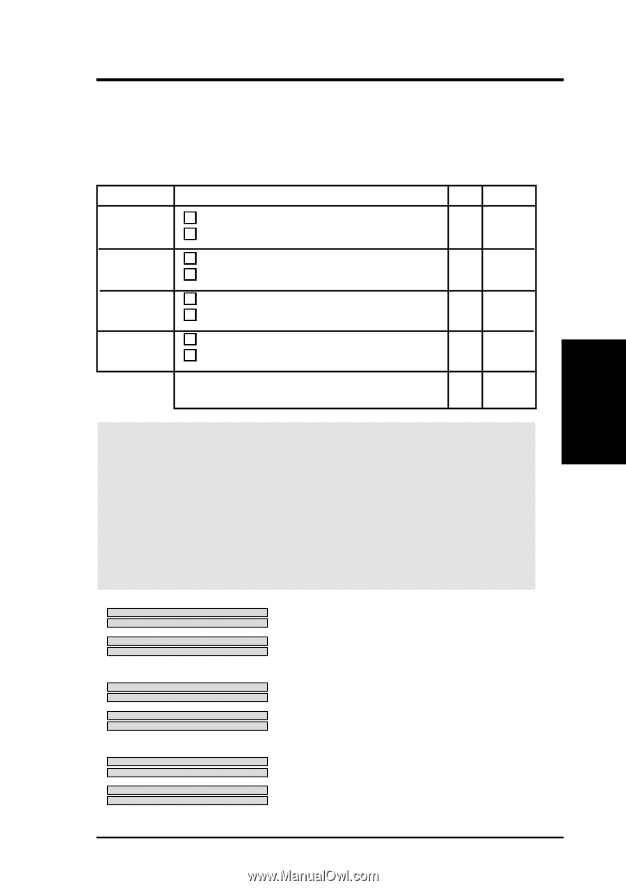
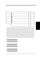
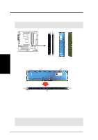
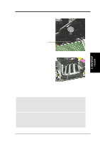
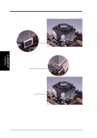
3. H/W SETUP System Memory 3. HARDWARE SETUP 3.4 System Memory NOTE: No hardware or BIOS setup is required after adding or removing memory. This motherboard has four 184-pin Rambus Inline Memory Modules (RIMM) sockets. These sockets support 64Mbit, 128Mbit, and 256Mbit Direct RDRAM technologies. Location Memory Module Subtotal RIMMA1 (Rows 0&1) RDRAM x 1 C-RIMM (use when socket will not be populated) RIMMA2 (Rows 2&3) RDRAM x 1 C-RIMM (use when socket will not be populated) RIMMB1 (Rows 4&5) RDRAM x 1 C-RIMM (use when socket will not be populated) RIMMB2 (Rows 6&7) RDRAM x 1 C-RIMM (use when socket will not be populated) TOTAL SYSTEM MEMORY = (2GB Max) IMPORTANT 1. The memory configuration of channel A (RIMMA1 and RIMMA2) and chan- nel B (RIMMB1 and RIMMB2) must be identical (see below). 2. C-RIMMs (Continuity RIMM) must be used to complete the sockets that are not populated by RDRAMs. A C-RIMM is necessary to avoid breaking the signal lines, which are a serial connection in a Rambus interface, such as used in this motherboard. This assures the electrical integrity of a Rambus interface. 3. When C-RIMMs are required, it is recommended that they be inserted into RIMMA2 and RIMMB2. a. C-RIMM RIMMB2 128MB RDRAM RIMMB1 NOTE: When using only two memory modules, C-RIMM RIMMA2 it is recommended that you use configuration a. 128MB RDRAM RIMMA1 b. 128MB RDRAM RIMMB2 C-RIMM RIMMB1 128MB RDRAM C-RIMM RIMMA2 RIMMA1 c. 128MB RDRAM RIMMB2 128MB RDRAM RIMMB1 128MB RDRAM 128MB RDRAM RIMMA2 RIMMA1 ASUS P4T-M User's Manual 17
-
 1
1 -
2
-
3
-
4
-
5
-
6
-
7
-
8
-
9
-
10
-
11
-
 12
12 -
 13
13 -
 14
14 -
 15
15 -
 16
16 -
 17
17 -
 18
18 -
 19
19 -
 20
20 -
 21
21 -
 22
22 -
23
-
24
-
25
-
26
-
27
-
28
-
29
-
30
-
31
-
32
-
33
-
34
-
35
-
36
-
37
-
38
-
39
-
40
-
41
-
42
-
43
-
44
-
45
-
46
-
47
-
48
-
49
-
50
-
51
-
52
-
53
-
54
-
55
-
56
-
57
-
58
-
59
-
60
-
61
-
62
-
63
-
64
-
65
-
66
-
67
-
68
-
69
-
70
-
71
-
72
-
73
-
74
-
75
-
76
-
77
-
78
-
79
-
80
-
81
-
82
-
83
-
84
-
85
-
86
-
87
-
88
 |
 |