Asus P4T-M P4T-M User Manual - Page 36
System Message LED Lead 2-pin MSG.LED - audio drivers
 |
View all Asus P4T-M manuals
Add to My Manuals
Save this manual to your list of manuals |
Page 36 highlights
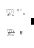
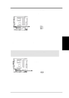
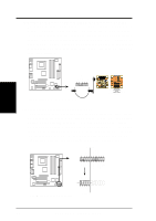
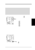
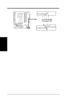
3. HARDWARE SETUP The following diagram is for items 22-28: Keyboard Lock Speaker Power LED Connector +5 V PLED Keylock Ground +5V Ground Ground Speaker +5 V MLED ExtSMI# Ground PWR Ground Reset Ground 3. H/W SETUP Connectors Reset SW Message LED P4T-M ATX Power SMI Lead Switch* * Requires an ATX power supply. P4T-M System Panel Connectors 22) System Power LED Lead (3-1 pin PWRLED) This 3-1 pin connector connects the system power LED, which lights when the system is powered on and blinks when it is in sleep mode. 23) Keyboard Lock Switch Lead (2-pin KEYLOCK) This 2-pin connector connects to the case-mounted key switch to allow keyboard locking. 24) System Warning Speaker Connector (4-pin SPEAKER) This 4-pin connector connects to the case-mounted speaker. Two sources (LINE_OUT and SPEAKER) will allow you to hear system beeps and warnings. Only SPEAKER will allow you to hear system beeps before the integrated audio has been properly initialized. 25) System Message LED Lead (2-pin MSG.LED) This indicates whether a message has been received from a fax/modem. The LED will remain lit when there is no signal and blink when there is data received. This function requires an ACPI OS and driver support. 26) System Management Interrupt Lead (2-pin SMI) This allows the user to manually place the system into a suspend mode or "Green" mode, where system activity is decreased to save electricity and expand the life of certain components when the system is not in use. This 2-pin connector connects to the case-mounted suspend switch. 27) ATX Power Switch Lead (2-pin PWRSW) The system power is controlled by a momentary switch connected to this lead. Pressing the button once will switch the system between ON and SOFT OFF. Pushing the switch while in the ON mode for more than 4 seconds will turn the system off. The system power LED shows the status of the system's power. 28) Reset Switch Lead (2-pin RESET) This 2-pin connector connects to the case-mounted reset switch for rebooting your computer without having to turn off your power switch. This is a preferred method of rebooting to prolong the life of the system's power supply. 36 ASUS P4T-M User's Manual
-
 1
1 -
2
-
3
-
4
-
5
-
6
-
7
-
8
-
9
-
10
-
11
-
12
-
13
-
14
-
15
-
16
-
17
-
18
-
19
-
20
-
21
-
22
-
23
-
24
-
25
-
26
-
27
-
28
-
29
-
30
-
 31
31 -
 32
32 -
 33
33 -
 34
34 -
 35
35 -
 36
36 -
 37
37 -
 38
38 -
 39
39 -
 40
40 -
 41
41 -
42
-
43
-
44
-
45
-
46
-
47
-
48
-
49
-
50
-
51
-
52
-
53
-
54
-
55
-
56
-
57
-
58
-
59
-
60
-
61
-
62
-
63
-
64
-
65
-
66
-
67
-
68
-
69
-
70
-
71
-
72
-
73
-
74
-
75
-
76
-
77
-
78
-
79
-
80
-
81
-
82
-
83
-
84
-
85
-
86
-
87
-
88
 |
 |
