Asus P4T-M P4T-M User Manual - Page 34
Standard and Consumer Infrared SIR Module Connector 5-pin IR - status
 |
View all Asus P4T-M manuals
Add to My Manuals
Save this manual to your list of manuals |
Page 34 highlights
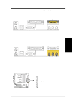
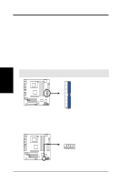
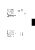
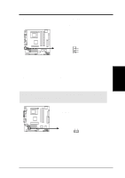
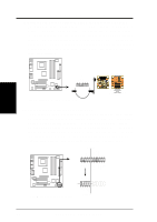
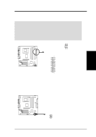
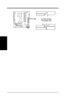
3. HARDWARE SETUP 18) Standard and Consumer Infrared (SIR) Module Connector (5-pin IR) This connector supports an optional wireless transmitting and receiving infrared module. This module mounts to a small opening on system cases that support this feature. You must also configure the setting through UART2 Use Infrared (see 4.4.2 I/O Device Configuration) to select whether UART2 is directed for use with COM2 or IrDA. Use the five pins as shown in Back View and connect a ribbon cable from the module to the motherboard's SIR connector according to the pin definitions. Front View Back View IR +5V (NC) IRRX GND IRTX 1 P4T-M P4T-M Infrared Module Connector IRTX +5V GND (NC) IRRX 19) Front Panel Connectors (24-1 pin AFPANEL) This connector allows you to setup an optional ASUS ipanel, an easy to access operational console mounted in a standard front drive bay. The iPanel offers front I/O ports, status LEDs and space reserved for a hard disk drive. (If you are not using an ASUS iPanel, you can connect an optional wireless transmitting and receiving infrared module to the SIR connector or an optional consumer infrared connector set to the CIR and SIR connectors for both wireless transmitting and remote control functions through one external infrared module.) AFPANEL 3. H/W SETUP Connectors +5 V IRRX GND IRTX SMBDATA +3VSB SMBCLK LOCKKEY NC NC NC NC GND NC CIRRX +5VSB CHASSIS# EXTSMI# +5V MLEDPCIRST# BATT NC +5 V IRRX GND IRTX NC GND NC CIRRX +5VSB P4T-M SIR CIR P4T-M Front Panel Connectors IR_CON 34 ASUS P4T-M User's Manual
-
 1
1 -
2
-
3
-
4
-
5
-
6
-
7
-
8
-
9
-
10
-
11
-
12
-
13
-
14
-
15
-
16
-
17
-
18
-
19
-
20
-
21
-
22
-
23
-
24
-
25
-
26
-
27
-
28
-
 29
29 -
 30
30 -
 31
31 -
 32
32 -
 33
33 -
 34
34 -
 35
35 -
 36
36 -
 37
37 -
 38
38 -
 39
39 -
40
-
41
-
42
-
43
-
44
-
45
-
46
-
47
-
48
-
49
-
50
-
51
-
52
-
53
-
54
-
55
-
56
-
57
-
58
-
59
-
60
-
61
-
62
-
63
-
64
-
65
-
66
-
67
-
68
-
69
-
70
-
71
-
72
-
73
-
74
-
75
-
76
-
77
-
78
-
79
-
80
-
81
-
82
-
83
-
84
-
85
-
86
-
87
-
88
 |
 |
