Asus P5GD2 Deluxe P5GD2 Deluxe user's manual - Page 56
P5GD2 Deluxe Chassis alarm lead, P5GD2 Deluxe Front panel connector
 |
View all Asus P5GD2 Deluxe manuals
Add to My Manuals
Save this manual to your list of manuals |
Page 56 highlights
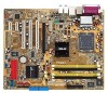
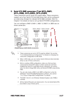
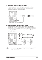
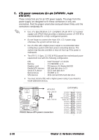
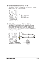
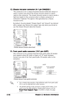
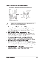
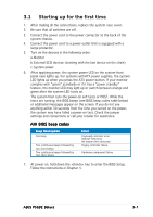
12. Chassis intrusion connector (4-1 pin CHASSIS1) This connector is for a chassis-mounted intrusion detection sensor or switch. Connect one end of the chassis intrusion sensor or switch cable to this connector. The chassis intrusion sensor or switch sends a high-level signal to this connector when a chassis component is removed or replaced. The signal is then generated as a chassis intrusion event. By default, the pins labeled "Chassis Signal" and "Ground" are shorted with a jumper cap. Remove the jumper caps only when you intend to use the chassis intrusion detection feature. CHASSIS1 ® +5VSB_MB Chassis Signal GND P5GD2 (Default) P5GD2 Deluxe Chassis alarm lead 13. Front panel audio connector (10-1 pin AAFP) This connector is for a chassis-mounted front panel audio I/O module that supports either HD Audio or legacy AC '97 audio standard. Connect one end of the front panel audio I/O module cable to this connector. P5GD2 AAFP Azalia-compliant pin definition AC'97-compliant pin definition SENSE2_RETUR SENSE1_RETUR PRESENCE# GND PORT2 L SENSE_SEND PORT2 R PORT1 R PORT1 L MIC2 MICPWR Line out_R NC Line out_L AGND +5VA BLINE_OUT_R BLINE_OUT_L 2-32 P5GD2 Deluxe Front panel connector • Use a chassis that provides a high-definition audio front panel audio I/O to use the high-definition audio features. • The default setting of this connector is legacy AC'97 audio, if you want to use the High-Definition (Azalia) audio features, set the F r o n t P a n e l S u p p o r t T y p e in the BIOS to Azalia. See page 4-26. Chapter 2: Hardware information
-
 1
1 -
2
-
3
-
4
-
5
-
6
-
7
-
8
-
9
-
10
-
11
-
12
-
13
-
14
-
15
-
16
-
17
-
18
-
19
-
20
-
21
-
22
-
23
-
24
-
25
-
26
-
27
-
28
-
29
-
30
-
31
-
32
-
33
-
34
-
35
-
36
-
37
-
38
-
39
-
40
-
41
-
42
-
43
-
44
-
45
-
46
-
47
-
48
-
49
-
50
-
 51
51 -
 52
52 -
 53
53 -
 54
54 -
 55
55 -
 56
56 -
 57
57 -
 58
58 -
 59
59 -
 60
60 -
 61
61 -
62
-
63
-
64
-
65
-
66
-
67
-
68
-
69
-
70
-
71
-
72
-
73
-
74
-
75
-
76
-
77
-
78
-
79
-
80
-
81
-
82
-
83
-
84
-
85
-
86
-
87
-
88
-
89
-
90
-
91
-
92
-
93
-
94
-
95
-
96
-
97
-
98
-
99
-
100
-
101
-
102
-
103
-
104
-
105
-
106
-
107
-
108
-
109
-
110
-
111
-
112
-
113
-
114
-
115
-
116
-
117
-
118
-
119
-
120
-
121
-
122
-
123
-
124
-
125
-
126
-
127
-
128
-
129
-
130
-
131
-
132
-
133
-
134
-
135
-
136
-
137
-
138
-
139
-
140
-
141
-
142
-
143
-
144
-
145
-
146
-
147
-
148
-
149
-
150
 |
 |