Asus RS300-H8-PS12 User Guide - Page 26
completely lifted., Position the CPU above the socket
 |
View all Asus RS300-H8-PS12 manuals
Add to My Manuals
Save this manual to your list of manuals |
Page 26 highlights
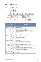
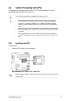
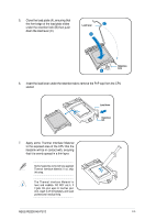
2. Press the load lever with your thumb (A), then move it to the right (B) until it is released from the retention tab. Do not remove the PnP cap yet from the CPU socket. Doing so may bend the pins of the socket. 3. Lift the load lever until the load plate is completely lifted. Load lever Retention tab Load plate 4. Position the CPU above the socket, ensuring that the gold triangle mark is on the bottom-left corner of the socket, then fit the CPU notches to the socket's alignment keys. The CPU fits in only one orientation. DO NOT force the CPU into the socket to prevent bending the pins on the socket and damaging the CPU. Gold triangle mark Alignment key CPU notches Alignment key 2-4 Chapter 2: Hardware setup
-
 1
1 -
2
-
3
-
4
-
5
-
6
-
7
-
8
-
9
-
10
-
11
-
12
-
13
-
14
-
15
-
16
-
17
-
18
-
19
-
20
-
 21
21 -
 22
22 -
 23
23 -
 24
24 -
 25
25 -
 26
26 -
 27
27 -
 28
28 -
 29
29 -
 30
30 -
 31
31 -
32
-
33
-
34
-
35
-
36
-
37
-
38
-
39
-
40
-
41
-
42
-
43
-
44
-
45
-
46
-
47
-
48
-
49
-
50
-
51
-
52
-
53
-
54
-
55
-
56
-
57
-
58
-
59
-
60
-
61
-
62
-
63
-
64
-
65
-
66
-
67
-
68
-
69
-
70
-
71
-
72
-
73
-
74
-
75
-
76
-
77
-
78
-
79
-
80
-
81
-
82
-
83
-
84
-
85
-
86
-
87
-
88
-
89
-
90
-
91
-
92
-
93
-
94
-
95
-
96
-
97
-
98
-
99
-
100
-
101
-
102
-
103
-
104
-
105
-
106
-
107
-
108
-
109
-
110
-
111
-
112
-
113
-
114
-
115
-
116
-
117
-
118
-
119
-
120
-
121
-
122
-
123
-
124
-
125
-
126
-
127
-
128
-
129
-
130
-
131
-
132
-
133
-
134
-
135
-
136
-
137
-
138
-
139
-
140
-
141
-
142
-
143
-
144
-
145
-
146
-
147
-
148
-
149
-
150
-
151
-
152
-
153
-
154
-
155
-
156
-
157
-
158
-
159
-
160
-
161
-
162
-
163
-
164
-
165
-
166
-
167
-
168
-
169
-
170
-
171
-
172
-
173
-
174
-
175
-
176
-
177
-
178
-
179
-
180
-
181
-
182
-
183
-
184
-
185
-
186
-
187
-
188
-
189
-
190
-
191
-
192
 |
 |
Chapter 2:
Hardware setup
2-4
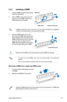
Do not remove the PnP cap yet from
the CPU socket. Doing so may bend
the pins of the socket.
2.
Press the load lever with your thumb
(A), then move it to the right (B) until it is
released from the retention tab.
Retention tab
Load lever
3.
Lift the load lever until the load plate is
completely lifted.
Load plate
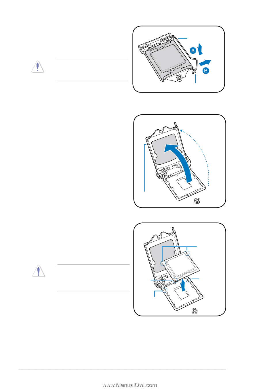
4.
Position the CPU above the socket,
ensuring that the gold triangle mark is on
the bottom-left corner of the socket, then fit
the CPU notches to the socket's alignment
keys.
The CPU fits in only one orientation. DO
NOT force the CPU into the socket to
prevent bending the pins on the socket
and damaging the CPU.
Gold
triangle
mark
CPU notches
Alignment
key
Alignment
key