Asus VINTAGE-AE1 Vintage-AE1 User''s Manual for English Edition - Page 38
Re-connecting cables
 |
View all Asus VINTAGE-AE1 manuals
Add to My Manuals
Save this manual to your list of manuals |
Page 38 highlights
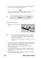
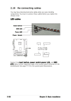
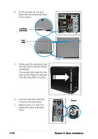
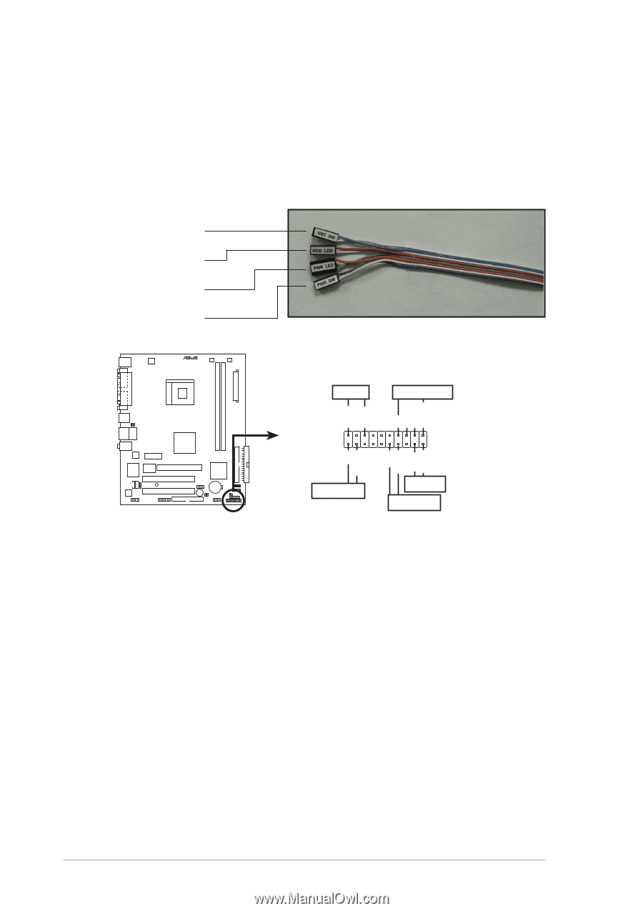
2.10 Re-connecting cables You may have disconnected some cables when you were installing components. You must re-connect these cables before you replace the chassis cover. LED cables Reset button HDD LED Power LED Power Switch ® PLED SPEAKER PLED+ PLED+5V Ground Ground Speaker PANEL +5V IDELED PWR Ground Reset Ground System panel connector IDE_LED RESET PWRSW * Requires an ATX power supply. Connect the r e s e t b u t t o n , p o w e r s w i t c h, p o w e r L E D , and H D D L E D cables to their respective leads in the system panel connector on the motherboard. See page 4-10 for the system panel descriptions. 2-20 Chapter 2: Basic installation
-
 1
1 -
2
-
3
-
4
-
5
-
6
-
7
-
8
-
9
-
10
-
11
-
12
-
13
-
14
-
15
-
16
-
17
-
18
-
19
-
20
-
21
-
22
-
23
-
24
-
25
-
26
-
27
-
28
-
29
-
30
-
31
-
32
-
 33
33 -
 34
34 -
 35
35 -
 36
36 -
 37
37 -
 38
38 -
 39
39 -
 40
40 -
 41
41 -
 42
42 -
 43
43 -
44
-
45
-
46
-
47
-
48
-
49
-
50
-
51
-
52
-
53
-
54
-
55
-
56
-
57
-
58
-
59
-
60
-
61
-
62
-
63
-
64
-
65
-
66
-
67
-
68
-
69
-
70
-
71
-
72
-
73
-
74
-
75
-
76
-
77
-
78
-
79
-
80
-
81
-
82
-
83
-
84
-
85
-
86
-
87
-
88
-
89
-
90
-
91
-
92
-
93
-
94
-
95
-
96
 |
 |
2-20
2-20
2-20
2-20
2-20
Chapter 2: Basic installation
Chapter 2: Basic installation
Chapter 2: Basic installation
Chapter 2: Basic installation
Chapter 2: Basic installation
2.10
Re-connecting cables
You may have disconnected some cables when you were installing
components. You must re-connect these cables before you replace the
chassis cover.
LED cables
LED cables
LED cables
LED cables
LED cables
System panel connector
*
Requires an ATX power supply.
PLED-
PWR
+5V
Speaker
PLED
Ground
RESET
Ground
Reset
Ground
Ground
PLED+
IDELED
+5V
IDE_LED
PWRSW
SPEAKER
PANEL
Connect the reset button, power switch
reset button, power switch
reset button, power switch
reset button, power switch
reset button, power switch, power LED,
power LED,
power LED,
power LED,
power LED, and HDD
HDD
HDD
HDD
HDD
LED
LED
LED
LED
LED cables to their respective leads in the system panel connector on the
motherboard. See page 4-10 for the system panel descriptions.
HDD LED
HDD LED
HDD LED
HDD LED
HDD LED
Power LED
Power LED
Power LED
Power LED
Power LED
Power
Switch
Power
Switch
Power
Switch
Power
Switch
Power
Switch
Reset button
Reset button
Reset button
Reset button
Reset button