Asus VINTAGE-AE1 Vintage-AE1 User''s Manual for English Edition - Page 58
Power LED Green 3-pin PLED
 |
View all Asus VINTAGE-AE1 manuals
Add to My Manuals
Save this manual to your list of manuals |
Page 58 highlights
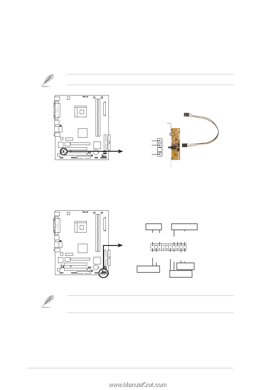
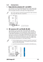
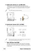
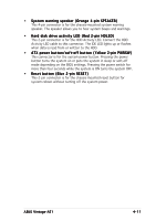
11. Digital audio connector (4-1 pin SPDIF_OUT) This connector is for an additional Sony/Philips Digital Interface (S/PDIF) port(s). Connect the S/PDIF module cable to this connector, then install the module to a slot opening at the back of the system chassis. The S/PDIF module is purchased separately. ® Digital audio connector SPDIF_OUT GND SPDIFOUT +5V 12. System panel connector (20-1 pin PANEL) This connector supports several chassis-mounted functions. ® PLED SPEAKER PLED+ PLED+5V Ground Ground Speaker System panel connector PANEL +5V IDELED PWR Ground Reset Ground IDE_LED RESET PWRSW * Requires an ATX power supply. The sytem panel connector is color-coded for easy connection. Refer to the connector description below for details. • Power LED (Green 3-pin PLED) This 3-pin connector is for the Power LED. Connect the 3-pin power LED cable from the system chassis to this connector. The LED lights up when you turn on the system power, and blinks when the system is in sleep mode. 4-10 Chapter 4: Motherboard info
-
 1
1 -
2
-
3
-
4
-
5
-
6
-
7
-
8
-
9
-
10
-
11
-
12
-
13
-
14
-
15
-
16
-
17
-
18
-
19
-
20
-
21
-
22
-
23
-
24
-
25
-
26
-
27
-
28
-
29
-
30
-
31
-
32
-
33
-
34
-
35
-
36
-
37
-
38
-
39
-
40
-
41
-
42
-
43
-
44
-
45
-
46
-
47
-
48
-
49
-
50
-
51
-
52
-
 53
53 -
 54
54 -
 55
55 -
 56
56 -
 57
57 -
 58
58 -
 59
59 -
 60
60 -
 61
61 -
 62
62 -
 63
63 -
64
-
65
-
66
-
67
-
68
-
69
-
70
-
71
-
72
-
73
-
74
-
75
-
76
-
77
-
78
-
79
-
80
-
81
-
82
-
83
-
84
-
85
-
86
-
87
-
88
-
89
-
90
-
91
-
92
-
93
-
94
-
95
-
96
 |
 |