Asus VINTAGE-AE1 Vintage-AE1 User''s Manual for English Edition - Page 54
Serial ATA connectors 7-pin SATA1, SATA2
 |
View all Asus VINTAGE-AE1 manuals
Add to My Manuals
Save this manual to your list of manuals |
Page 54 highlights
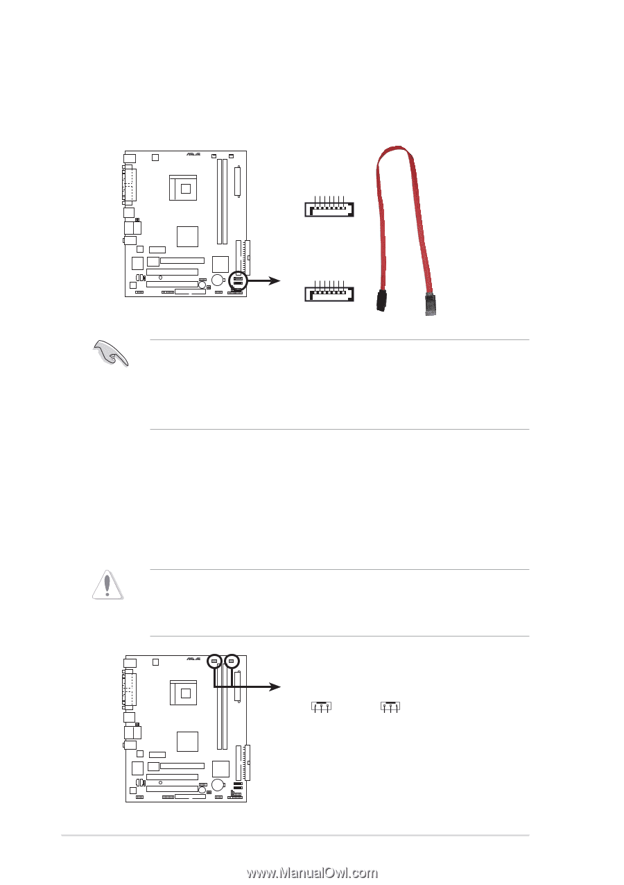
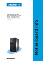
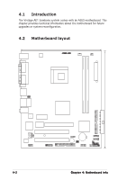
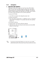
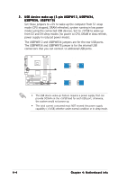
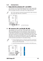
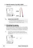
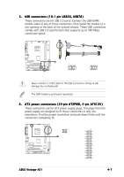
3 . Serial ATA connectors (7-pin SATA1, SATA2) These connectors are for the Serial ATA signal cables for Serial ATA hard disk drives. ® SATA2 GND RSATA_RXN2 RSATA_RXP2 GND RSATA_TXN2 RSATA_TXP2 GND GND RSATA_RXN1 RSATA_RXP1 GND RSATA_TXN1 RSATA_TXP1 GND SATA connectors SATA1 Important notes on Serial ATA • You must install Windows® 2000 Service Pack 4 or the Windows® XP Service Pack1 before using Serial ATA hard disk drives. • When using the connectors in standard IDE mode, connect the primary (boot) hard disk drive to the SATA1 or SATA2 connector. 4. CPU and Chassis Fan connectors (3-pin CPU_FAN, 3-pin CHA_FAN) The fan connectors support cooling fans of 350 mA~740 mA (8.88 W max.) or a total of 1 A~2.22 A (26.64 W max.) at +12V. Connect the fan cables to the fan connectors on the motherboard, making sure that the black wire of each cable matches the ground pin of the connector. Do not forget to connect the fan cables to the fan connectors. Insufficient air flow inside the system may damage the motherboard components. These are not jumpers! Do not place jumper caps on the fan connectors! ® CHA_FAN CPU_FAN Rotation +12V GND Rotation +12V GND Fan connectors 4-6 Chapter 4: Motherboard info
-
 1
1 -
2
-
3
-
4
-
5
-
6
-
7
-
8
-
9
-
10
-
11
-
12
-
13
-
14
-
15
-
16
-
17
-
18
-
19
-
20
-
21
-
22
-
23
-
24
-
25
-
26
-
27
-
28
-
29
-
30
-
31
-
32
-
33
-
34
-
35
-
36
-
37
-
38
-
39
-
40
-
41
-
42
-
43
-
44
-
45
-
46
-
47
-
48
-
 49
49 -
 50
50 -
 51
51 -
 52
52 -
 53
53 -
 54
54 -
 55
55 -
 56
56 -
 57
57 -
 58
58 -
 59
59 -
60
-
61
-
62
-
63
-
64
-
65
-
66
-
67
-
68
-
69
-
70
-
71
-
72
-
73
-
74
-
75
-
76
-
77
-
78
-
79
-
80
-
81
-
82
-
83
-
84
-
85
-
86
-
87
-
88
-
89
-
90
-
91
-
92
-
93
-
94
-
95
-
96
 |
 |