Axis Communications P1224-E P1214-E Network Camera - User Manual - Page 4
Connectors and Buttons - axis network camera
 |
View all Axis Communications P1224-E manuals
Add to My Manuals
Save this manual to your list of manuals |
Page 4 highlights
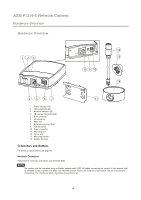
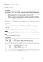
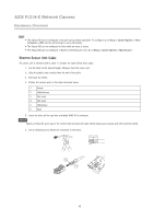
AXIS P1214-E Network Camera Hardware Overview Hardware Overview 1 23 12 13 8 9 10 14 4 5 67 11 1 Power indicator LED 2 Status indicator LED 3 Network indicator LED 4 SD card slot (microSD card) 5 RJ12 connector 6 I/O connector 7 Main unit 8 Network connector (PoE) 9 Control button 10 Power connector 11 Mounting rail 12 Sensor unit 13 Mounting bracket 14 Outdoor housing Connectors and Buttons For technical specifications, see page 45. Network Connector RJ45 Ethernet connector with Power over Ethernet (PoE). NOTICE The product shall be connected using a shielded network cable (STP). All cables connecting the product to the network shall be intended for their specific use. Make sure that the network devices are installed in accordance with the manufacturer's instructions. For information about regulatory requirements, see . 4
-
 1
1 -
 2
2 -
 3
3 -
 4
4 -
 5
5 -
 6
6 -
 7
7 -
 8
8 -
 9
9 -
 10
10 -
11
-
12
-
13
-
14
-
15
-
16
-
17
-
18
-
19
-
20
-
21
-
22
-
23
-
24
-
25
-
26
-
27
-
28
-
29
-
30
-
31
-
32
-
33
-
34
-
35
-
36
-
37
-
38
-
39
-
40
-
41
-
42
-
43
-
44
-
45
-
46
-
47
-
48
-
49
 |
 |
