Axis Communications P1224-E P1214-E Network Camera - User Manual - Page 47
Connectors
 |
View all Axis Communications P1224-E manuals
Add to My Manuals
Save this manual to your list of manuals |
Page 47 highlights
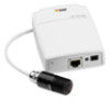
AXIS P1214-E Network Camera Technical Specifications Connectors I/O Connector 4-pin terminal block for: • Auxiliary power (DC output) • Digital Input • Digital Output • 0 V DC (-) 4 3 2 1 Function 0 V DC (-) DC output Digital Input Digital Output Pin Notes Specifications 1 0 V DC 2 Can be used to power auxiliary equipment. Note: This pin can only be used as power out. 3.3 V DC Max load = 50 mA 3 Connect to pin 1 to activate, or leave floating (unconnected) 0 to max 40 V DC to deactivate 4 Connected to pin 1 when activated, floating (unconnected) 0 to max 40 V DC, open drain, when deactivated. If used with an inductive load, e.g. a relay, 100 mA a diode must be connected in parallel with the load, for protection against voltage transients. 1 3.3 Vmax 50 mA 2 3 4 47
-
 1
1 -
2
-
3
-
4
-
5
-
6
-
7
-
8
-
9
-
10
-
11
-
12
-
13
-
14
-
15
-
16
-
17
-
18
-
19
-
20
-
21
-
22
-
23
-
24
-
25
-
26
-
27
-
28
-
29
-
30
-
31
-
32
-
33
-
34
-
35
-
36
-
37
-
38
-
39
-
40
-
41
-
 42
42 -
 43
43 -
 44
44 -
 45
45 -
 46
46 -
 47
47 -
 48
48 -
 49
49
 |
 |
