Axis Communications P1224-E P1214-E Network Camera - User Manual - Page 6
Shorten Sensor Unit Cable
 |
View all Axis Communications P1224-E manuals
Add to My Manuals
Save this manual to your list of manuals |
Page 6 highlights
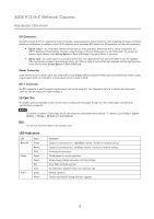
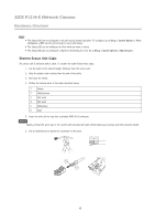
AXIS P1214-E Network Camera Hardware Overview Note • The Status LED can be configured to be unlit during normal operation. To configure, go to Setup > System Options > Ports & Devices > LED. See the online help for more information. • The Status LED can be configured to flash while an event is active. • The Status LED can be configured to flash for identifying the unit. Go to Setup > System Options > Maintenance . Shorten Sensor Unit Cable The sensor unit is delivered with a cable. To shorten the cable follow these steps: 1. Cut the cable to the desired length. Measure from the sensor unit. 2. Strip the plastic outer coating from the end of the cable. 3. Peel back the shield. 4. Flatten the colored wires in the order described below. 1 Brown 2 White/brown 3 Not used 4 Not used 5 White/blue 6 Blue 5. Insert the wires all the way into a shielded 6P6C RJ12 connector. NOTICE Make sure that the wires stay in the correct order and that the cable shield makes good contact with the connector shield. 6. Use a crimping tool to fasten the connector to the cable. 14 mm 14 mm 6 1 6
-
 1
1 -
 2
2 -
 3
3 -
 4
4 -
 5
5 -
 6
6 -
 7
7 -
 8
8 -
 9
9 -
 10
10 -
 11
11 -
 12
12 -
13
-
14
-
15
-
16
-
17
-
18
-
19
-
20
-
21
-
22
-
23
-
24
-
25
-
26
-
27
-
28
-
29
-
30
-
31
-
32
-
33
-
34
-
35
-
36
-
37
-
38
-
39
-
40
-
41
-
42
-
43
-
44
-
45
-
46
-
47
-
48
-
49
 |
 |
