Belkin F1DA104Q User Manual - Page 21
Example of Daisy-Chain Configuration, Getting Started
 |
UPC - 722868650004
View all Belkin F1DA104Q manuals
Add to My Manuals
Save this manual to your list of manuals |
Page 21 highlights
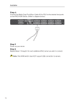
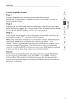
section Installation Example of Daisy-Chain Configuration 1 2 cable 1 Primary unit (BANK 00) 3 4 Secondary unit (BANK 01) cable 2 5 6 Secondary unit (BANK 02) cable 3 7 Secondary unit (BANK 03) 8 Getting Started: Step 1: Make sure that all servers and PRO3 KVM Switches are powered off and that each PRO3 KVM Switch has been assigned a unique BANK address. Step 2: Place all primary and secondary KVM switches in the desired location. Step 3: Connect the console monitor, keyboard, and mouse to the console ports of the primary switch (BANK 00). Refer to "Connecting the Console to the PRO3 KVM Switch" on page 14. 19
-
 1
1 -
2
-
3
-
4
-
5
-
6
-
7
-
8
-
9
-
10
-
11
-
12
-
13
-
14
-
15
-
 16
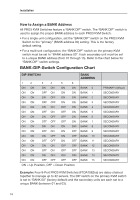
16 -
 17
17 -
 18
18 -
 19
19 -
 20
20 -
 21
21 -
 22
22 -
 23
23 -
 24
24 -
 25
25 -
 26
26 -
27
-
28
-
29
-
30
-
31
-
32
-
33
-
34
-
35
-
36
-
37
-
38
-
39
-
40
-
41
-
42
-
43
-
44
 |
 |

1
2
3
4
5
6
7
8
section
19
Installation
Example of Daisy-Chain Configuration
cable 1
cable 2
cable 3
Primary unit
(BANK 00)
Secondary unit (
BANK 01)
Secondary unit (
BANK 02)
Secondary unit (
BANK 03)
Getting Started:
Step 1:
Make sure that all servers and PRO3 KVM Switches are powered off and
that each PRO3 KVM Switch has been assigned a unique BANK address.
Step 2:
Place all primary and secondary KVM switches in the desired location.
Step 3:
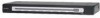
Connect the console monitor, keyboard, and mouse to the console ports
of the primary switch (BANK 00). Refer to “Connecting the Console to the PRO3
KVM Switch” on page 14.