Belkin F1DA104Q User Manual - Page 23
Connecting the Servers, Step 1, Step 2
 |
UPC - 722868650004
View all Belkin F1DA104Q manuals
Add to My Manuals
Save this manual to your list of manuals |
Page 23 highlights
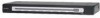
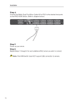
section Installation Connecting the Servers: 1 Step 1: Connect all servers to the primary and secondary KVM switches. 2 Refer to the "Connecting PS/2 Servers to the PRO3 KVM Switch" section on page 15 for instructions. Step 2: 3 Power up the secondary KVM switches sequentially, beginning with the highest BANK, by connecting each unit's power supply. Each KVM switch should display 4 its corresponding BANK-address number as it is powered up. Step 3: 5 Power up the primary switch. You should see the primary KVM switch light up and display the digits "00", indicating its BANK address. 6 Note: If the PRO3 KVM Switches do not enumerate correctly, reset the primary KVM switch (BANK 00) by simultaneously pressing the "BANK +" and "BANK -" buttons. You can also reset the primary KVM switch to detect newly 7 added secondary KVM switches. If the KVM switches still do not enumerate correctly, check that all KVM switches have the correct BANK address assigned 8 to them and that all daisy-chain cables are connected properly. Step 4: Verify that the primary KVM switch has detected all secondary KVM switches by scrolling through the BANKs using the "BANK +" and "BANK -" buttons. If all secondary KVM switches are detected properly, the LED display on the primary KVM switch will register and display the BANK address of the attached secondary KVM switch. 21
-
 1
1 -
2
-
3
-
4
-
5
-
6
-
7
-
8
-
9
-
10
-
11
-
12
-
13
-
14
-
15
-
16
-
17
-
 18
18 -
 19
19 -
 20
20 -
 21
21 -
 22
22 -
 23
23 -
 24
24 -
 25
25 -
 26
26 -
 27
27 -
 28
28 -
29
-
30
-
31
-
32
-
33
-
34
-
35
-
36
-
37
-
38
-
39
-
40
-
41
-
42
-
43
-
44
 |
 |
