Beretta Stampede Old West Beretta Stampede User Manual - Page 37
Disassembly
 |
View all Beretta Stampede Old West manuals
Add to My Manuals
Save this manual to your list of manuals |
Page 37 highlights
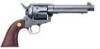
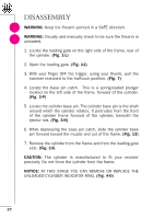
DISASSEMBLY ! WARNING: Keep the firearm pointed in a SAFE direction. ! WARNING: Visually and manually check to be sure the firearm is unloaded. 1. Locate the loading gate on the right side of the frame, rear of the cylinder. (Fig. 1-L) 2. Open the loading gate. (Fig. 11) 3. With your finger OFF the trigger, using your thumb, pull the hammer rearward to the half-cock position. (Fig. 7) 4. Locate the base pin catch. This is a spring-loaded plunger located on the left side of the frame, forward of the cylinder. (Fig. 3-P) 5. Locate the cylinder base pin. The cylinder base pin is the shaft around which the cylinder rotates. It protrudes from the front of the cylinder frame forward of the cylinder, beneath the ejector rod. (Fig. 3-N) 6. While depressing the base pin catch, slide the cylinder base pin forward toward the muzzle and out of the frame. (Fig. 13) 7. Remove the cylinder from the frame and from the loading gate side. (Fig. 14) CAUTION: The cylinder is manufactured to fit your revolver precisely. Do not force the cylinder from the frame. NOTICE: AT THIS STAGE YOU CAN REMOVE OR REPLACE THE UNLOADED-CYLINDER INDICATOR RING. (Fig. 4-O) 37
-
 1
1 -
2
-
3
-
4
-
5
-
6
-
7
-
8
-
9
-
10
-
11
-
12
-
13
-
14
-
15
-
16
-
17
-
18
-
19
-
20
-
21
-
22
-
23
-
24
-
25
-
26
-
27
-
28
-
29
-
30
-
31
-
 32
32 -
 33
33 -
 34
34 -
 35
35 -
 36
36 -
 37
37 -
 38
38 -
 39
39 -
 40
40 -
 41
41 -
 42
42 -
43
 |
 |
