Bernina 530 Manual - Page 13
Ernin
 |
View all Bernina 530 manuals
Add to My Manuals
Save this manual to your list of manuals |
Page 13 highlights
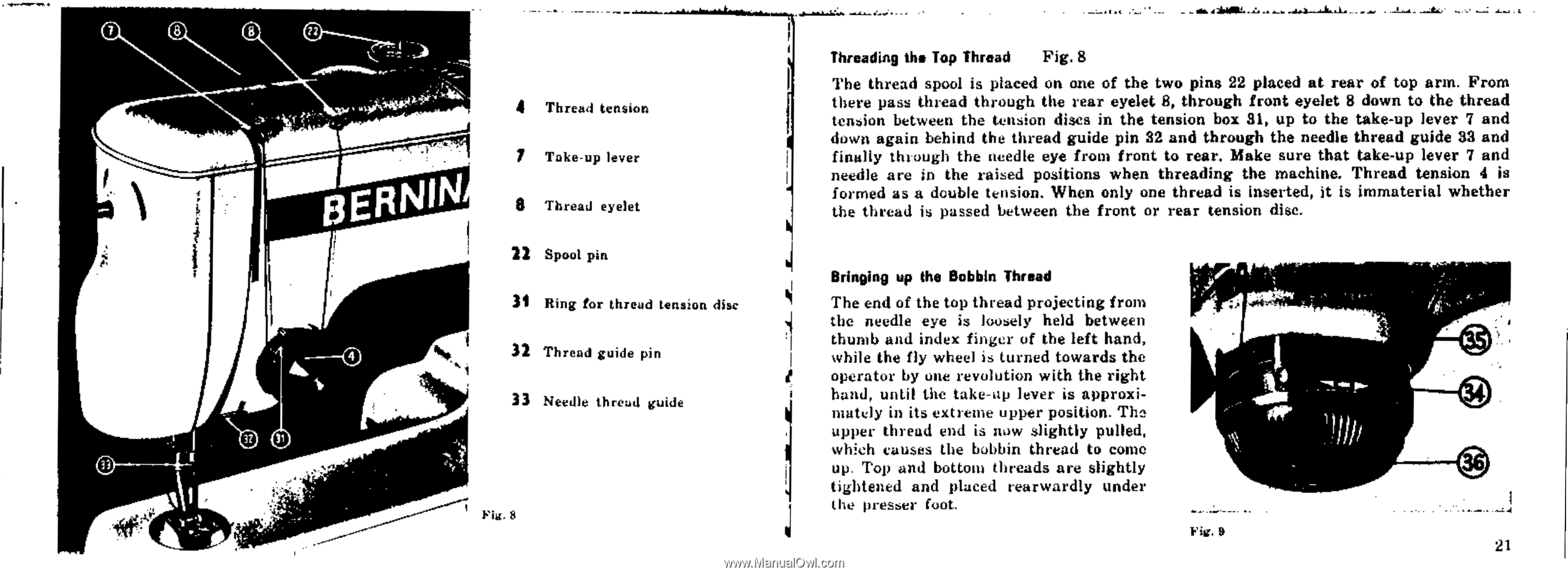
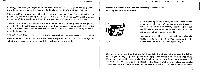
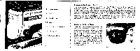
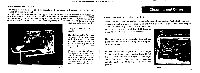
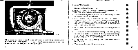
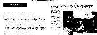
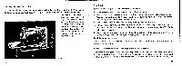
O 8 8 t2 .i 4 33 . y id ERNIN 4 Thread tension 7 Take-up lever 8 Thread eyelet 22 Spool pin 31 Ring for thread tension disc 32 Thread guide pin 33 Needle thread guide Fig. 8 Threading the Top Thread Fig. 8 The thread spool is placed on one of the two pins 22 placed at rear of top arm. From there pass thread through the rear eyelet 8, through front eyelet 8 down to the thread tension between the tension discs in the tension box 31, up to the take-up lever 7 and down again behind the thread guide pin 32 and through the needle thread guide 33 and finally the ough the needle eye from front to rear. Make sure that take-up lever 7 and needle are in the raised positions when threading the machine. Thread tension 4 is formed as a double tension. When only one thread is inserted, it is immaterial whether the thread is passed between the front or rear tension disc. Bringing up the Bobbin Thread The end of the top thread projecting from the needle eye is loosely held between thumb and index finger of the left hand, while the fly wheel is turned towards the operator by one revolution with the right hand, until the take-op lever is approximately in its extreme upper position. T11a upper thread end is now slightly pulled, which causes the bobbin thread to come up. Top and bottom threads are slightly tightened and placed rearwardly under the presser foot. Fig. 9 21
-
 1
1 -
2
-
3
-
4
-
5
-
6
-
7
-
 8
8 -
 9
9 -
 10
10 -
 11
11 -
 12
12 -
 13
13 -
 14
14 -
 15
15 -
 16
16 -
 17
17 -
 18
18 -
19
-
20
-
21
-
22
-
23
-
24
-
25
-
26
-
27
-
28
-
29
-
30
-
31
-
32
-
33
-
34
-
35
-
36
-
37
-
38
-
39
-
40
-
41
-
42
-
43
-
44
-
45
-
46
-
47
-
48
-
49
-
50
-
51
-
52
-
53
-
54
 |
 |