Bernina 530 Manual - Page 8
Displacement
 |
View all Bernina 530 manuals
Add to My Manuals
Save this manual to your list of manuals |
Page 8 highlights
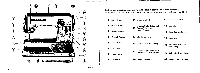
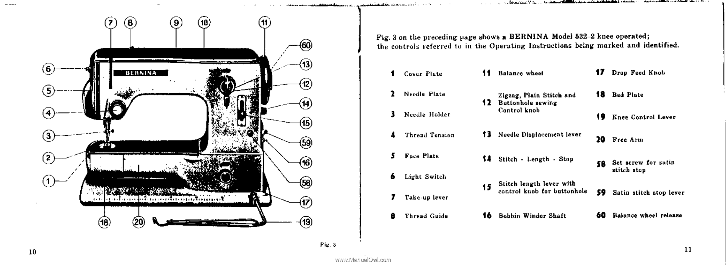
cio 10 11 13 BERNINA 12 0 a 3 2 14 15 'a • et) :1•72 7 7. 17 18 20 19 Fig. 3 on the preceding page shows a BERNINA Mode) 532-2 knee operated; the controls referred to in the Operating Instructions being marked and identified. 1 Cover Plate 2 Needle Plate 3 Needle Holder 4 Thread Tension 5 Face Plate 6 Light Switch 7 Take-up lever Thread Guide 11 Balance wheel 17 Drop Feed Knob Zigzag, Plain Stitch and 12 Buttonhole sewing Control knob 18 Bed Plate 19 Knee Control Lever 13 Needle Displacement lever 20 Free Arm 14 Stitch - Length - Stop se Set screw for satin stitch stop 15 Stitch length lever with control knob for buttonhole S9 Satin stitch atop lever 16 Bobbin Winder Shaft 60 Balance wheel release Fig. 3 11
-
 1
1 -
2
-
 3
3 -
 4
4 -
 5
5 -
 6
6 -
 7
7 -
 8
8 -
 9
9 -
 10
10 -
 11
11 -
 12
12 -
 13
13 -
14
-
15
-
16
-
17
-
18
-
19
-
20
-
21
-
22
-
23
-
24
-
25
-
26
-
27
-
28
-
29
-
30
-
31
-
32
-
33
-
34
-
35
-
36
-
37
-
38
-
39
-
40
-
41
-
42
-
43
-
44
-
45
-
46
-
47
-
48
-
49
-
50
-
51
-
52
-
53
-
54
 |
 |
0
3
2
cio
10
11
BERNINA
a
'a
•
:
1
•
72
7
7.
18
20
13
12
14
15
et)
17
19
Fig.
3
on
the
preceding
page
shows
a
BERNINA
Mode)
532-2
knee
operated;
the
controls
referred
to
in
the
Operating
Instructions
being
marked
and
identified.
1
Cover
Plate
11
Balance
wheel
17
Drop
Feed
Knob
2
Needle
Plate
Zigzag,
Plain
Stitch
and
18
Bed
Plate
12
Buttonhole
sewing
Control
knob
3
Needle
Holder
19
Knee
Control
Lever
4
Thread
Tension
13
Needle
Displacement
lever
20
Free
Arm
5
Face
Plate
14
Stitch
-
Length
-
Stop
se
Set
screw
for
satin
stitch
stop
6
Light
Switch
15
Stitch
length
lever
with
control
knob
for
buttonhole
S9
Satin
stitch
atop
lever
7
Take-up
lever
Thread
Guide
16
Bobbin
Winder
Shaft
60
Balance
wheel
release
Fig.
3
11