Bose A20 Aviation Owner's guide - Page 35
Mounting the aircraft panel connector
 |
View all Bose A20 Aviation manuals
Add to My Manuals
Save this manual to your list of manuals |
Page 35 highlights
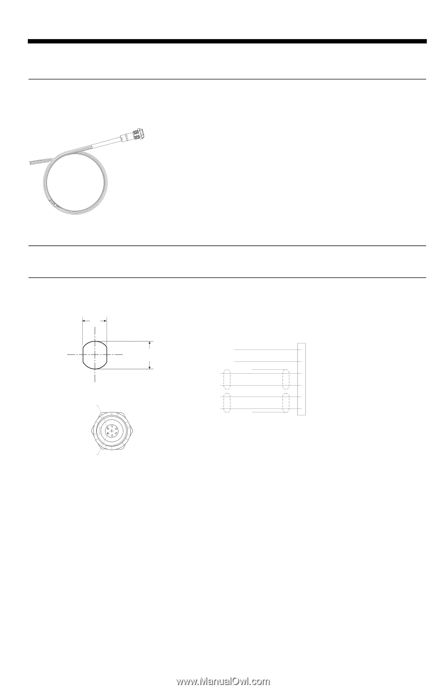
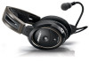
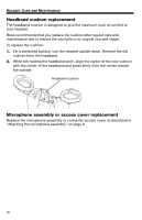
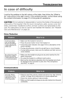
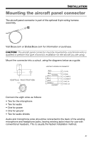
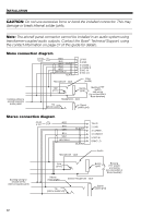
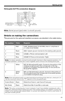
English Tab 2, 10 Tab 3, 11 Tab 4, 12 Tab 5, 13 Tab 6, 14 Tab 7, 15 Tab 8, 16 INSTALLATION Mounting the aircraft panel connector The aircraft panel connector is part of the optional 6-pin wiring harness assembly. Visit Bose.com or Global.Bose.com for information or purchase. CAUTION: The aircraft panel connector must be mounted by a technician who is qualified to perform this type of avionics installation for the aircraft you are using. Mount the connector into a cutout, using the diagrams below as a guide. 12.5mm .49" AIRCRAFT INTERFACE SCHEMATIC 14.0mm .55" RECEPTACLE - PINOUT (FRONT VIEW) Pin 6 RED BLK WHT BLK/WH BLU WHT WH/BLU BLK/WH • 1 V+IN • 2 GND • 3 COMM L • 4 COMM R • 5 MIC HI • 6 MIC LO Pin 1 Connect the eight wires as follows: • Two for the microphone • Two for audio • One for power • One for ground • Two for audio shields Audio and microphone wires should be connected to the back of the existing microphone and headphone jacks, leaving existing jacks intact for use with conventional headsets. This is usually the fastest installation method. 31
-
 1
1 -
2
-
3
-
4
-
5
-
6
-
7
-
8
-
9
-
10
-
11
-
12
-
13
-
14
-
15
-
16
-
17
-
18
-
19
-
20
-
21
-
22
-
23
-
24
-
25
-
26
-
27
-
28
-
29
-
 30
30 -
 31
31 -
 32
32 -
 33
33 -
 34
34 -
 35
35 -
 36
36 -
 37
37 -
 38
38 -
 39
39 -
 40
40 -
41
-
42
-
43
-
44
 |
 |