Bose A20 Aviation Owner's guide - Page 36
Technical Support
 |
View all Bose A20 Aviation manuals
Add to My Manuals
Save this manual to your list of manuals |
Page 36 highlights
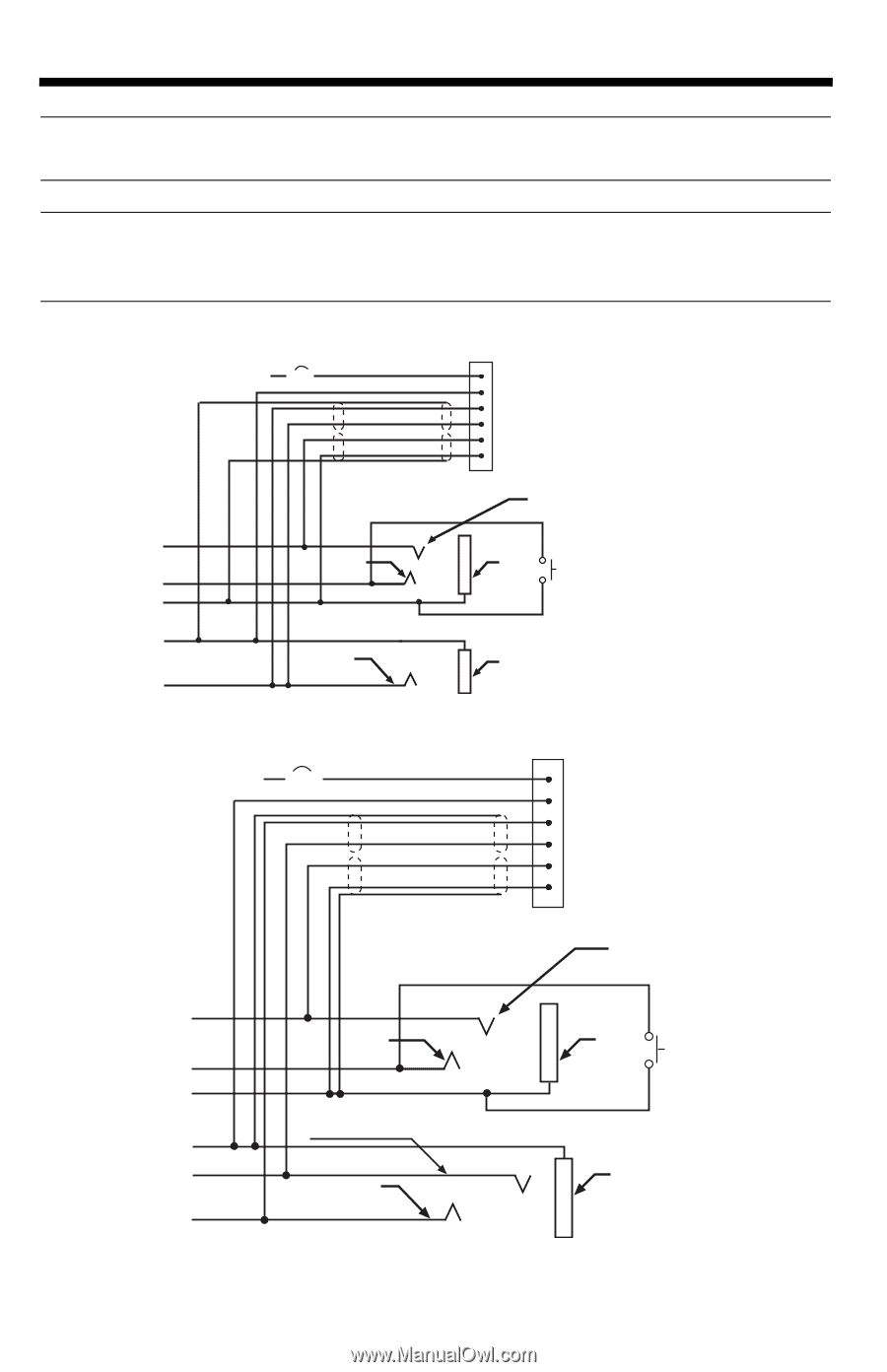
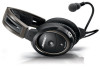
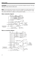
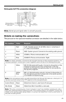
Tab 8, 16 Tab 7, 15 Tab 6, 14 Tab 5, 13 Tab 4, 12 Tab 3, 11 Tab2, 10 English INSTALLATION CAUTION: Do not use excessive force or bend the installed connector. This may damage or break internal solder joints. Note: The aircraft panel connector cannot be installed in an audio system using transformer-coupled audio outputs. Contact the Bose® Technical Support, using the contact information on page 37 of this guide for details. Mono connection diagram 10-32 V DC 1/2A RED BLK WHT BLK/WH BLU WHT WHT/BLU BLK/WH Microphone - Jack 1V+IN 2 GND 3 COMM L 4 COMM R 5 MIC HI 6 MIC LO Ring (audio) Existing wiring to aircraft intercom/ audio panel TPP (PTT) Barrel (gnd) Headphone - Jack Existing PTT switch and wiring (no connection to Bose headset) Tip (phone audio) Barrel (audio gnd) Stereo connection diagram 10-32 V DC 1/2A RED BLK WHT BLU WHT WHT/BLU BLK/WH BLK/WH Microphone - Jack 1V+IN 2 GND 3 COMM L 4 COMM R 5 MIC HI 6 MIC LO Audio Existing wiring to aircraft stereo intercom/audio panel TPP (PTT) Phone audio (right) Barrel (gnd) Stereo Headphone - Jack Existing PTT switch and wiring (no connection to Bose headset) Tip (phone audio left) Barrel (audio gnd) 32
-
 1
1 -
2
-
3
-
4
-
5
-
6
-
7
-
8
-
9
-
10
-
11
-
12
-
13
-
14
-
15
-
16
-
17
-
18
-
19
-
20
-
21
-
22
-
23
-
24
-
25
-
26
-
27
-
28
-
29
-
30
-
 31
31 -
 32
32 -
 33
33 -
 34
34 -
 35
35 -
 36
36 -
 37
37 -
 38
38 -
 39
39 -
 40
40 -
 41
41 -
42
-
43
-
44
 |
 |