Brother International MFC-9200C Users Manual - English - Page 36
Connecting the MFC, SET CARTRIDGES, PLS OPEN COVER - ink cartridge
 |
View all Brother International MFC-9200C manuals
Add to My Manuals
Save this manual to your list of manuals |
Page 36 highlights
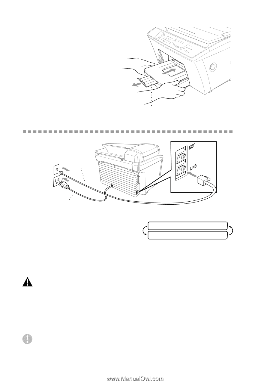
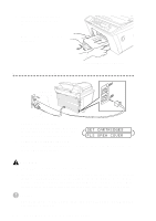
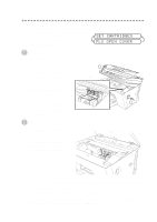
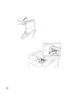
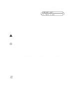
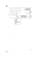
6 Slide the paper cassette into the MFC until it locks into place. 7 Pull out the paper output tray extension. Connecting the MFC Paper Output Tray Extension Telephone Line Cord Power Cord 1 Connect the power cord. There is no ON/OFF switch. When you plug in the power cord, the power goes on and the LCD alternately shows: SET CARTRIDGES PLS OPEN COVER 2 Connect the telephone line cord. Connect one end of the telephone line cord to the jack on the MFC and the other end to a modular wall jack. WARNING s The MFC must be grounded using a 3-prong plug. s Since the MFC is grounded through the power outlet, protect yourself from potentially hazardous electrical conditions on the telephone line by keeping the MFC's power turned on when you connect it to a telephone line. When you want to move your MFC, protect yourself by disconnecting the telephone line first, and then the power cord. Caution Operating the MFC before you install the ink cartridges will permanently damage the print head. 2-8 ASSEMBLY AND CONNECTIONS
-
 1
1 -
2
-
3
-
4
-
5
-
6
-
7
-
8
-
9
-
10
-
11
-
12
-
13
-
14
-
15
-
16
-
17
-
18
-
19
-
20
-
21
-
22
-
23
-
24
-
25
-
26
-
27
-
28
-
29
-
30
-
 31
31 -
 32
32 -
 33
33 -
 34
34 -
 35
35 -
 36
36 -
 37
37 -
 38
38 -
 39
39 -
 40
40 -
 41
41 -
42
-
43
-
44
-
45
-
46
-
47
-
48
-
49
-
50
-
51
-
52
-
53
-
54
-
55
-
56
-
57
-
58
-
59
-
60
-
61
-
62
-
63
-
64
-
65
-
66
-
67
-
68
-
69
-
70
-
71
-
72
-
73
-
74
-
75
-
76
-
77
-
78
-
79
-
80
-
81
-
82
-
83
-
84
-
85
-
86
-
87
-
88
-
89
-
90
-
91
-
92
-
93
-
94
-
95
-
96
-
97
-
98
-
99
-
100
-
101
-
102
-
103
-
104
-
105
-
106
-
107
-
108
-
109
-
110
-
111
-
112
-
113
-
114
-
115
-
116
-
117
-
118
-
119
-
120
-
121
-
122
-
123
-
124
-
125
-
126
-
127
-
128
-
129
-
130
-
131
-
132
-
133
-
134
-
135
-
136
-
137
-
138
-
139
-
140
-
141
-
142
-
143
-
144
-
145
-
146
-
147
-
148
-
149
-
150
-
151
-
152
-
153
-
154
-
155
-
156
-
157
-
158
-
159
-
160
-
161
-
162
-
163
-
164
-
165
-
166
-
167
-
168
-
169
-
170
-
171
-
172
-
173
-
174
-
175
-
176
-
177
-
178
-
179
-
180
-
181
-
182
-
183
-
184
-
185
-
186
-
187
-
188
-
189
-
190
-
191
-
192
-
193
-
194
-
195
-
196
-
197
-
198
-
199
-
200
-
201
-
202
-
203
-
204
-
205
-
206
-
207
-
208
-
209
-
210
-
211
-
212
-
213
-
214
-
215
-
216
-
217
-
218
-
219
-
220
-
221
-
222
-
223
-
224
-
225
-
226
-
227
-
228
-
229
-
230
-
231
-
232
-
233
-
234
-
235
-
236
-
237
-
238
-
239
-
240
-
241
-
242
-
243
-
244
 |
 |