Brother International PE535 Operation Manual - Page 7
Getting Ready
 |
View all Brother International PE535 manuals
Add to My Manuals
Save this manual to your list of manuals |
Page 7 highlights
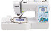
1 Chapter Names of Machine Parts GETTING READY Names of Machine Parts ■ Main parts bcd a e f l k g j i m t s h n o p 1 Bobbin winding thread guide and pretension disk (page 13) 2 Thread guide (page 12) 3 Spool cap (page 11) 4 Spool pin (page 11) 5 Bobbin winder (page 11) 6 LCD (liquid crystal display) (page 10) 7 Operation panel (page 6) 8 Operation buttons (page 6) 9 Embroidery unit (page 19) 0 Thread cutter (page 16) A Needle threader lever (page 17) B Thread tension dial (page 28) C Handwheel Turn the handwheel toward you (counterclockwise) to raise and lower the needle to embroider one stitch. D Thread guide cover (page 12) E Handle Carry the machine by its handle when transporting. F Presser foot lever Raise and lower the presser foot lever to raise and lower the presser foot. G Main power switch (page 9) H Power supply jack (page 9) I Air vent The air vent allows the air surrounding the motor to circulate. Do not cover the air vent while the machine is being used. J USB port (for a USB flash drive) (page 36) GETTING READY 1 q r 5
-
 1
1 -
 2
2 -
 3
3 -
 4
4 -
 5
5 -
 6
6 -
 7
7 -
 8
8 -
 9
9 -
 10
10 -
 11
11 -
 12
12 -
13
-
14
-
15
-
16
-
17
-
18
-
19
-
20
-
21
-
22
-
23
-
24
-
25
-
26
-
27
-
28
-
29
-
30
-
31
-
32
-
33
-
34
-
35
-
36
-
37
-
38
-
39
-
40
-
41
-
42
-
43
-
44
-
45
-
46
-
47
-
48
-
49
-
50
-
51
-
52
 |
 |
