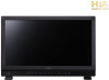
Canon DP-V2420 User Manual - Page 16
Procedures to attach/detach stands
 |
View all Canon DP-V2420 manuals
Add to My Manuals
Save this manual to your list of manuals |
Page 16 highlights
Procedures to attach/detach stands The main unit comes with two stands which can be detached. The position where the front stand is attached can be changed. CAUTION • Use a flat, clear surface when attaching/detaching the stands. • The display can tip over if the stand has not been attached. • Avoid touching the screen during this step as it may damage it. ■■ Detaching 1. Place the display with the screen facing down on a soft cloth or cushioning material that is larger than the display. 2. Front stand: Remove the mounting screws (two each) from the left and right stands. Rear stand: Remove the mounting screws (one each) from the left and right stands. Do not lose the removed screws. Do not use these screws for other purposes. ■■ Attaching 1. Place the display with the screen facing down on a soft cloth or cushioning material that is larger than the display. 2. Align the position of the stand and screw hole on the video display. Alight the convex part of the stand and concave part of the video display. 3. Front stand: Fix the left and right stands using the mounting screws (two each). Rear stand: Fix the left and right stands using the mounting screws (one each). Rear Concave part Rear stand Convex part Front stand mounting part (inside) Screen side Concave part Front stand mounting part (outside) Front stand mounting screw hole Convex part Mounting screw Front stand Note • It is recommended to mount both front stands in either the outside or inside positions. 16 Installation/Connection
-
 1
1 -
2
-
3
-
4
-
5
-
6
-
7
-
8
-
9
-
10
-
 11
11 -
 12
12 -
 13
13 -
 14
14 -
 15
15 -
 16
16 -
 17
17 -
 18
18 -
 19
19 -
 20
20 -
 21
21 -
22
-
23
-
24
-
25
-
26
-
27
-
28
-
29
-
30
-
31
-
32
-
33
-
34
-
35
-
36
-
37
-
38
-
39
-
40
-
41
-
42
-
43
-
44
-
45
-
46
-
47
-
48
-
49
-
50
-
51
-
52
-
53
-
54
-
55
-
56
-
57
-
58
-
59
-
60
-
61
-
62
-
63
-
64
-
65
-
66
-
67
-
68
-
69
-
70
-
71
-
72
-
73
-
74
-
75
-
76
-
77
-
78
-
79
-
80
-
81
-
82
-
83
-
84
-
85
-
86
-
87
-
88
-
89
-
90
-
91
-
92
-
93
-
94
-
95
-
96
-
97
-
98
-
99
-
100
-
101
-
102
-
103
-
104
-
105
-
106
-
107
-
108
 |
 |
