Canon PC400 Service Manual - Page 113
I. Power Supply
 |
View all Canon PC400 manuals
Add to My Manuals
Save this manual to your list of manuals |
Page 113 highlights
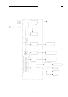
CHAPTER 7 EXTERNALS/AUXILIARY MECHANISMS I. POWER SUPPLY A. Outline Power switch (SW604) Door switch Delivery door (SW1) switch (SW2) Microprocessor FU102 +DC5VL Sub power supply Relay RL101 AC driver FU101 Lamp drive +24VU assembly indicates AC line. Fixing heater Scanning lamp HVT assembly +24VR +24VU DC power supply +24VR assembly +5V T106 Main transformer DC controller/DC power supply PCB Figure 7-101A Charging roller Developing cylinder Motor driver assembly Main motor (M1) DC load Solenoids, etc. Control panel Sensor Photointerrupter COPYRIGHT © 1998 CANON INC. CANON PC400/420/430,FC200/220 REV.0 JAN.1998 PRINTED IN JAPAN (IMPRIME AU JAPON) 7-1
-
 1
1 -
2
-
3
-
4
-
5
-
6
-
7
-
8
-
9
-
10
-
11
-
12
-
13
-
14
-
15
-
16
-
17
-
18
-
19
-
20
-
21
-
22
-
23
-
24
-
25
-
26
-
27
-
28
-
29
-
30
-
31
-
32
-
33
-
34
-
35
-
36
-
37
-
38
-
39
-
40
-
41
-
42
-
43
-
44
-
45
-
46
-
47
-
48
-
49
-
50
-
51
-
52
-
53
-
54
-
55
-
56
-
57
-
58
-
59
-
60
-
61
-
62
-
63
-
64
-
65
-
66
-
67
-
68
-
69
-
70
-
71
-
72
-
73
-
74
-
75
-
76
-
77
-
78
-
79
-
80
-
81
-
82
-
83
-
84
-
85
-
86
-
87
-
88
-
89
-
90
-
91
-
92
-
93
-
94
-
95
-
96
-
97
-
98
-
99
-
100
-
101
-
102
-
103
-
104
-
105
-
106
-
107
-
 108
108 -
 109
109 -
 110
110 -
 111
111 -
 112
112 -
 113
113 -
 114
114 -
 115
115 -
 116
116 -
 117
117 -
 118
118 -
119
-
120
-
121
-
122
-
123
-
124
-
125
-
126
-
127
-
128
-
129
-
130
-
131
-
132
-
133
-
134
-
135
-
136
-
137
-
138
-
139
-
140
-
141
-
142
-
143
-
144
-
145
-
146
-
147
-
148
-
149
-
150
-
151
-
152
-
153
-
154
-
155
-
156
-
157
-
158
-
159
-
160
-
161
-
162
-
163
-
164
-
165
-
166
-
167
-
168
-
169
-
170
-
171
-
172
-
173
-
174
-
175
-
176
-
177
-
178
-
179
-
180
-
181
-
182
-
183
-
184
-
185
-
186
-
187
-
188
-
189
-
190
-
191
-
192
-
193
-
194
-
195
-
196
-
197
 |
 |

COPYRIGHT © 1998 CANON INC.
CANON PC400/420/430,FC200/220 REV.0 JAN.1998 PRINTED IN JAPAN (IMPRIME AU JAPON)
CHAPTER 7 EXTERNALS/AUXILIARY MECHANISMS
7-1
I. POWER SUPPLY
A.
Outline
Figure 7-101A
Power switch
(SW604)
Microprocessor
indicates AC line.
Door switch
(SW1)
Sub power
supply
Relay
AC driver
Fixing heater
Lamp drive
assembly
Scanning lamp
HVT
assembly
Charging roller
Developing cylinder
Main motor (M1)
DC load
Control panel
Solenoids, etc.
Photointerrupter
DC power
supply
assembly
Motor driver
assembly
DC controller/DC power supply PCB
FU101
FU102
RL101
+DC5VL
+24VR
+24VU
+24VR
+5V
T106
Main transformer
Sensor
Delivery door
switch (SW2)
+24VU