Canon PC400 Service Manual - Page 61
C. Primary Charging Control Circuit, Outline, Reference - toner for
 |
View all Canon PC400 manuals
Add to My Manuals
Save this manual to your list of manuals |
Page 61 highlights
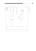
CHPTER 4 IMAGE FORMATION SYSTEM C. Primary Charging Control Circuit 1. Outline Figure 4-101C shows the circuit that controls the primary charging, and the circuit has the following functions: • Turns the DC bias ON and OFF. • Turns the AC bias ON and OFF. • Controls the DC bias voltage (constant). • Controls the AC bias current (constant). A DC bias (-625 V/-230 V) and an AC bias are applied to the primary charging roller to maintain the surface potential of the photosensitive drum uniform. During document exposure (-625 V) and non-exposure periods (-230 V) DC bias is switched by the DC bias high output command (HVPHO). The DC bias and AC bias are turned ON and OFF by the DC bias ON command (HVPDC) and AC bias ON command (HVPAC), respectively. Reference: Unless the document is being illuminated, the DC bias is switched to -230V to prevent adhesion of toner on the photosensitive drum. COPYRIGHT © 1998 CANON INC. CANON PC400/420/430,FC200/220 REV.0 JAN.1998 PRINTED IN JAPAN (IMPRIME AU JAPON) 4-3
-
 1
1 -
2
-
3
-
4
-
5
-
6
-
7
-
8
-
9
-
10
-
11
-
12
-
13
-
14
-
15
-
16
-
17
-
18
-
19
-
20
-
21
-
22
-
23
-
24
-
25
-
26
-
27
-
28
-
29
-
30
-
31
-
32
-
33
-
34
-
35
-
36
-
37
-
38
-
39
-
40
-
41
-
42
-
43
-
44
-
45
-
46
-
47
-
48
-
49
-
50
-
51
-
52
-
53
-
54
-
55
-
 56
56 -
 57
57 -
 58
58 -
 59
59 -
 60
60 -
 61
61 -
 62
62 -
 63
63 -
 64
64 -
 65
65 -
 66
66 -
67
-
68
-
69
-
70
-
71
-
72
-
73
-
74
-
75
-
76
-
77
-
78
-
79
-
80
-
81
-
82
-
83
-
84
-
85
-
86
-
87
-
88
-
89
-
90
-
91
-
92
-
93
-
94
-
95
-
96
-
97
-
98
-
99
-
100
-
101
-
102
-
103
-
104
-
105
-
106
-
107
-
108
-
109
-
110
-
111
-
112
-
113
-
114
-
115
-
116
-
117
-
118
-
119
-
120
-
121
-
122
-
123
-
124
-
125
-
126
-
127
-
128
-
129
-
130
-
131
-
132
-
133
-
134
-
135
-
136
-
137
-
138
-
139
-
140
-
141
-
142
-
143
-
144
-
145
-
146
-
147
-
148
-
149
-
150
-
151
-
152
-
153
-
154
-
155
-
156
-
157
-
158
-
159
-
160
-
161
-
162
-
163
-
164
-
165
-
166
-
167
-
168
-
169
-
170
-
171
-
172
-
173
-
174
-
175
-
176
-
177
-
178
-
179
-
180
-
181
-
182
-
183
-
184
-
185
-
186
-
187
-
188
-
189
-
190
-
191
-
192
-
193
-
194
-
195
-
196
-
197
 |
 |
