Canon PC400 Service Manual - Page 66
Turning the DC Bias ON and OFF and Controlling the Voltage Level
 |
View all Canon PC400 manuals
Add to My Manuals
Save this manual to your list of manuals |
Page 66 highlights
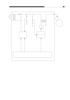
CHPTER 4 IMAGE FORMATION SYSTEM 2. Operations Figure 4-104D shows the circuit that controls the developing bias, and the circuit has the following functions: • Turns the developing bias AC component ON and OFF. • Turns the developing bias DC component ON and OFF. • Controls the voltage level of the DC bias according to the settings made by the copy density dial/lever. a. Turning the Developing Bias AC Component ON and OFF • ACBTP=0 (pulse output OFF) T104 goes OFF. The above condition deprives the developing cylinder of the AC bias. • ACBTP=1 (pulse output ON) T104 goes ON. The above condition raises the AC bias output using the high-voltage transformer (T104) and sends it to the developing cylinder. b. Turning the DC Bias ON and OFF and Controlling the Voltage Level The DC bias is turned ON and OFF by the DC bias control command (DCBPWM). The microprocessor checks the DC voltage when the DC bias is ON so as to keep it to the specified voltage. a) DCBPWM=0 (DC bias OFF) Q146 goes ON. DC bias goes OFF. b) DCBPWM=1 (DC bias ON) Q146 goes OFF. DC bias goes ON. The voltage level of the DC bias is controlled by varying the pulse width of the DC bias control command (DCBPWM). While the photosensitive drum is rotating except during development, about -400 V is applied to the developing cylinder. 4-8 COPYRIGHT © 1998 CANON INC. CANON PC400/420/430,FC200/220 REV.0 JAN.1998 PRINTED IN JAPAN (IMPRIME AU JAPON)
-
 1
1 -
2
-
3
-
4
-
5
-
6
-
7
-
8
-
9
-
10
-
11
-
12
-
13
-
14
-
15
-
16
-
17
-
18
-
19
-
20
-
21
-
22
-
23
-
24
-
25
-
26
-
27
-
28
-
29
-
30
-
31
-
32
-
33
-
34
-
35
-
36
-
37
-
38
-
39
-
40
-
41
-
42
-
43
-
44
-
45
-
46
-
47
-
48
-
49
-
50
-
51
-
52
-
53
-
54
-
55
-
56
-
57
-
58
-
59
-
60
-
 61
61 -
 62
62 -
 63
63 -
 64
64 -
 65
65 -
 66
66 -
 67
67 -
 68
68 -
 69
69 -
 70
70 -
 71
71 -
72
-
73
-
74
-
75
-
76
-
77
-
78
-
79
-
80
-
81
-
82
-
83
-
84
-
85
-
86
-
87
-
88
-
89
-
90
-
91
-
92
-
93
-
94
-
95
-
96
-
97
-
98
-
99
-
100
-
101
-
102
-
103
-
104
-
105
-
106
-
107
-
108
-
109
-
110
-
111
-
112
-
113
-
114
-
115
-
116
-
117
-
118
-
119
-
120
-
121
-
122
-
123
-
124
-
125
-
126
-
127
-
128
-
129
-
130
-
131
-
132
-
133
-
134
-
135
-
136
-
137
-
138
-
139
-
140
-
141
-
142
-
143
-
144
-
145
-
146
-
147
-
148
-
149
-
150
-
151
-
152
-
153
-
154
-
155
-
156
-
157
-
158
-
159
-
160
-
161
-
162
-
163
-
164
-
165
-
166
-
167
-
168
-
169
-
170
-
171
-
172
-
173
-
174
-
175
-
176
-
177
-
178
-
179
-
180
-
181
-
182
-
183
-
184
-
185
-
186
-
187
-
188
-
189
-
190
-
191
-
192
-
193
-
194
-
195
-
196
-
197
 |
 |
