Canon PC400 Service Manual - Page 116
A. External Covers, A, Detaching the Control Panel Cover
 |
View all Canon PC400 manuals
Add to My Manuals
Save this manual to your list of manuals |
Page 116 highlights
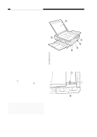
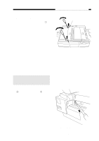
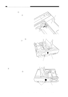
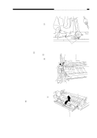
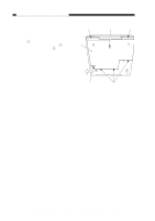
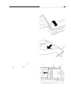
CHAPTER 7 EXTERNALS/AUXILIARY MECHANISMS A. External Covers Detach the covers as follows to Å clean, inspect, or repair the inside of the machine. 1. Detaching the Control Panel Cover 1) Move the copyboard cover to the left until it stops. 2) Open the top cover, and remove the screw q. 3) Detach the control cover w as if to lift it to the front. Ä Ã q Control panel cover w Bottom cover e Top cover r Body cover t Delivery assembly cover y Copyboard cover À Á Â Figure 7-201A À Note: When attaching the PC400/FC200 control panel cover, fit the VR on the control panel PCB into the groove of the density control lever. Á Figure 7-202A 7-4 COPYRIGHT © 1998 CANON INC. CANON PC400/420/430,FC200/220 REV.0 JAN.1998 PRINTED IN JAPAN (IMPRIME AU JAPON)
-
 1
1 -
2
-
3
-
4
-
5
-
6
-
7
-
8
-
9
-
10
-
11
-
12
-
13
-
14
-
15
-
16
-
17
-
18
-
19
-
20
-
21
-
22
-
23
-
24
-
25
-
26
-
27
-
28
-
29
-
30
-
31
-
32
-
33
-
34
-
35
-
36
-
37
-
38
-
39
-
40
-
41
-
42
-
43
-
44
-
45
-
46
-
47
-
48
-
49
-
50
-
51
-
52
-
53
-
54
-
55
-
56
-
57
-
58
-
59
-
60
-
61
-
62
-
63
-
64
-
65
-
66
-
67
-
68
-
69
-
70
-
71
-
72
-
73
-
74
-
75
-
76
-
77
-
78
-
79
-
80
-
81
-
82
-
83
-
84
-
85
-
86
-
87
-
88
-
89
-
90
-
91
-
92
-
93
-
94
-
95
-
96
-
97
-
98
-
99
-
100
-
101
-
102
-
103
-
104
-
105
-
106
-
107
-
108
-
109
-
110
-
 111
111 -
 112
112 -
 113
113 -
 114
114 -
 115
115 -
 116
116 -
 117
117 -
 118
118 -
 119
119 -
 120
120 -
 121
121 -
122
-
123
-
124
-
125
-
126
-
127
-
128
-
129
-
130
-
131
-
132
-
133
-
134
-
135
-
136
-
137
-
138
-
139
-
140
-
141
-
142
-
143
-
144
-
145
-
146
-
147
-
148
-
149
-
150
-
151
-
152
-
153
-
154
-
155
-
156
-
157
-
158
-
159
-
160
-
161
-
162
-
163
-
164
-
165
-
166
-
167
-
168
-
169
-
170
-
171
-
172
-
173
-
174
-
175
-
176
-
177
-
178
-
179
-
180
-
181
-
182
-
183
-
184
-
185
-
186
-
187
-
188
-
189
-
190
-
191
-
192
-
193
-
194
-
195
-
196
-
197
 |
 |

COPYRIGHT © 1998 CANON INC.
CANON PC400/420/430,FC200/220 REV.0 JAN.1998 PRINTED IN JAPAN (IMPRIME AU JAPON)
7-4
CHAPTER 7 EXTERNALS/AUXILIARY MECHANISMS
A. External Covers
Detach the covers as follows to
clean, inspect, or repair the inside of the
machine.
Figure 7-202A
q
Control panel cover
w
Bottom cover
e
Top cover
r
Body cover
t
Delivery assembly cover
y
Copyboard cover
Figure 7-201A
1.
Detaching the Control Panel Cover
1)
Move the copyboard cover to the left
until it stops.
2)
Open the top cover, and remove the
screw
q
.
3)
Detach the control cover
w
as if to lift
it to the front.
À
`
´
ˆ
˜
¯
À
`
Note:
When attaching the PC400/FC200
control panel cover, fit the VR on
the control panel PCB into the
groove of the density control lever.