Canon PC400 Service Manual - Page 71
E, Transfer positive DC bias ON command TREV
 |
View all Canon PC400 manuals
Add to My Manuals
Save this manual to your list of manuals |
Page 71 highlights
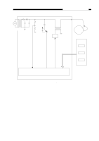
CHPTER 4 IMAGE FORMATION SYSTEM Photosensitive drum Transfer charging roller Transformer (T106) Positive bias control circuit Oscillation circuit 24V Voltage control circuit Transformer (T107) Multiplier/ Rectifier circuit Constant current control circuit Current sensor circuit Pulse/DC converter circuit Current limiter circuit Transfer positive DC bias ON command (TREV) Voltage sensor (analog signal) Transfer DC bias ON command (HVTDC) Transfer DC bias control command (DCTPWM) Microprocessor DC controller/DC power supply PCB Figure 4-101E COPYRIGHT © 1998 CANON INC. CANON PC400/420/430,FC200/220 REV.0 JAN.1998 PRINTED IN JAPAN (IMPRIME AU JAPON) 4-13
-
 1
1 -
2
-
3
-
4
-
5
-
6
-
7
-
8
-
9
-
10
-
11
-
12
-
13
-
14
-
15
-
16
-
17
-
18
-
19
-
20
-
21
-
22
-
23
-
24
-
25
-
26
-
27
-
28
-
29
-
30
-
31
-
32
-
33
-
34
-
35
-
36
-
37
-
38
-
39
-
40
-
41
-
42
-
43
-
44
-
45
-
46
-
47
-
48
-
49
-
50
-
51
-
52
-
53
-
54
-
55
-
56
-
57
-
58
-
59
-
60
-
61
-
62
-
63
-
64
-
65
-
 66
66 -
 67
67 -
 68
68 -
 69
69 -
 70
70 -
 71
71 -
 72
72 -
 73
73 -
 74
74 -
 75
75 -
 76
76 -
77
-
78
-
79
-
80
-
81
-
82
-
83
-
84
-
85
-
86
-
87
-
88
-
89
-
90
-
91
-
92
-
93
-
94
-
95
-
96
-
97
-
98
-
99
-
100
-
101
-
102
-
103
-
104
-
105
-
106
-
107
-
108
-
109
-
110
-
111
-
112
-
113
-
114
-
115
-
116
-
117
-
118
-
119
-
120
-
121
-
122
-
123
-
124
-
125
-
126
-
127
-
128
-
129
-
130
-
131
-
132
-
133
-
134
-
135
-
136
-
137
-
138
-
139
-
140
-
141
-
142
-
143
-
144
-
145
-
146
-
147
-
148
-
149
-
150
-
151
-
152
-
153
-
154
-
155
-
156
-
157
-
158
-
159
-
160
-
161
-
162
-
163
-
164
-
165
-
166
-
167
-
168
-
169
-
170
-
171
-
172
-
173
-
174
-
175
-
176
-
177
-
178
-
179
-
180
-
181
-
182
-
183
-
184
-
185
-
186
-
187
-
188
-
189
-
190
-
191
-
192
-
193
-
194
-
195
-
196
-
197
 |
 |

COPYRIGHT © 1998 CANON INC.
CANON PC400/420/430,FC200/220 REV.0 JAN.1998 PRINTED IN JAPAN (IMPRIME AU JAPON)
CHPTER 4 IMAGE FORMATION SYSTEM
4-13
Figure 4-101E
Oscillation
circuit
Voltage
control
circuit
Positive
bias
control
circuit
Multiplier/
Rectifier circuit
Constant current
control circuit
Pulse/DC
converter
circuit
Current
sensor
circuit
Current
limiter
circuit
Microprocessor
Photo-
sensitive
drum
Transfer
charging
roller
Transformer
(T106)
Transformer (T107)
DC controller/DC power supply PCB
Transfer positive DC bias ON command (TREV)
Voltage sensor (analog signal)
Transfer DC bias ON command (HVTDC)
Transfer DC bias control
command (DCTPWM)
24V