Canon PowerShot A95 PowerShot A95 Camera User Guide - Page 14
Components Guide - user guide
 |
View all Canon PowerShot A95 manuals
Add to My Manuals
Save this manual to your list of manuals |
Page 14 highlights
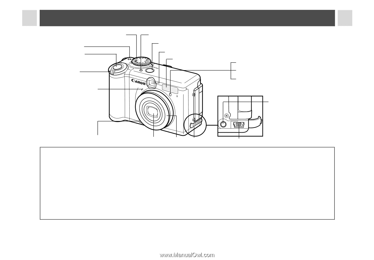
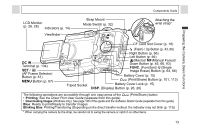
Components Guide Shooting Mode Dial (p. 39) Speaker Shutter Button (p. 34) Zoom Lever (p. 34, 47, 58, 59, 60) Microphone Power Lamp (p. 14) ON/OFF Button (p. 31) Viewfinder Window (p. 36) Flash (p. 43) AF-assist Beam (p. 36) Red-eye Reduction Lamp (p. 44) Self-timer Lamp (p. 46) A/V (Audio/Video) Out Terminal (p. 117) Ring Release Button Lens Ring Terminal Cover DIGITAL Terminal (p. 111) The following cables are used to connect the camera to a computer or printer. Computer: Interface Cable IFC-400PCU (supplied with the camera) Direct Print Compatible Printers (Sold Separately) • CP Printers: Interface Cable IFC-400PCU (supplied with the camera) or the Direct Interface Cable DIF-100 (supplied with the CP-100/CP-10) • Bubble Jet Printers: - Bubble Jet Direct Compatible Printers: Please refer to your Bubble Jet printer user guide. - PictBridge Compliant Printers: Interface Cable IFC-400PCU (supplied with the camera) • PictBridge Compliant Non-Canon Printers: Interface Cable IFC-400PCU (supplied with the camera) Please refer to the System Map or the Direct Print User Guide supplied with the camera for direct print compatible printer information. 12
-
 1
1 -
2
-
3
-
4
-
5
-
6
-
7
-
8
-
 9
9 -
 10
10 -
 11
11 -
 12
12 -
 13
13 -
 14
14 -
 15
15 -
 16
16 -
 17
17 -
 18
18 -
 19
19 -
20
-
21
-
22
-
23
-
24
-
25
-
26
-
27
-
28
-
29
-
30
-
31
-
32
-
33
-
34
-
35
-
36
-
37
-
38
-
39
-
40
-
41
-
42
-
43
-
44
-
45
-
46
-
47
-
48
-
49
-
50
-
51
-
52
-
53
-
54
-
55
-
56
-
57
-
58
-
59
-
60
-
61
-
62
-
63
-
64
-
65
-
66
-
67
-
68
-
69
-
70
-
71
-
72
-
73
-
74
-
75
-
76
-
77
-
78
-
79
-
80
-
81
-
82
-
83
-
84
-
85
-
86
-
87
-
88
-
89
-
90
-
91
-
92
-
93
-
94
-
95
-
96
-
97
-
98
-
99
-
100
-
101
-
102
-
103
-
104
-
105
-
106
-
107
-
108
-
109
-
110
-
111
-
112
-
113
-
114
-
115
-
116
-
117
-
118
-
119
-
120
-
121
-
122
-
123
-
124
-
125
-
126
-
127
-
128
-
129
-
130
-
131
-
132
-
133
-
134
-
135
-
136
-
137
-
138
-
139
-
140
-
141
-
142
-
143
-
144
-
145
-
146
-
147
-
148
-
149
-
150
-
151
-
152
-
153
-
154
-
155
-
156
-
157
-
158
-
159
-
160
-
161
-
162
-
163
 |
 |