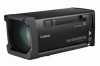
Canon UHD DIGISUPER 90 manual for UJ27x6.5B - Page 42
Mounting the Switch Box Option, Mounting the Accessories for IS, Operation, Only Models with IS,
 |
View all Canon UHD DIGISUPER 90 manuals
Add to My Manuals
Save this manual to your list of manuals |
Page 42 highlights
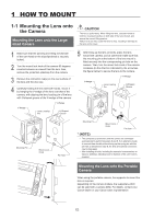
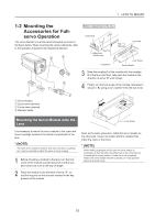
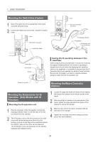
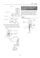
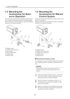
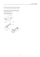
1 HOW TO MOUNT Mounting the Switch Box (Option) 1 Mount the switch box to the panhandle of the tripod, using the attached clamp. 2 Connect the switch box to the lens, using the included cable. Lens "SW. BOX" Connector Switch Box Cable Lens "AUX (IS Controller)" Connector IS Operation Switch Fixing Belts IS Indicator Unit (or Viewfinder) Switch Box Pan Handle Clamp Seeing the IS operating statuses in the viewfinder When using a camera provided with a function for receiving the signals indicating that the IS function is operating or stopped from the lens side and displaying this operating status on its viewfinder, it is possible to connect only the IS Operation Switch and operate it to perform these functions. Remove the IS indicator unit that is connected partway along the cable from the IS operation unit. Clamp fixing knob Mounting the Macro Controller (Option) Mounting the Accessories for IS Operation (Only Models with IS Function) Mounting the IS operation unit 1 Plug the connector of the IS operation unit into the receptacle labeled "AUX" on the left side of the lens (as viewed from the camera). 2 The IS Indicator unit on the other branch of the cable comes with an anchoring screw. Mount it to the location (such as on the edge of the viewfinder) where the ON/OFF status of the LEDs can be observed. The IS indicator unit is not necessary for the camera equipped with display function. 1 Loosen the large and small lock knobs of the clamper, then mount the clamper to the left pan handle of the tripod. 2 After mounting the clamper to the pan handle of the tripod, tighten the large and small lock knobs of the clamper to secure the clamper. 3 Mate the rose joint of the macro controller with the rose joint of the clamper. 4 Tighten the mounting knob of the clamper to firmly secure the zoom demand. E4
-
 1
1 -
2
-
3
-
4
-
5
-
6
-
7
-
8
-
9
-
10
-
11
-
12
-
13
-
14
-
15
-
16
-
17
-
18
-
19
-
20
-
21
-
22
-
23
-
24
-
25
-
26
-
27
-
28
-
29
-
30
-
31
-
32
-
33
-
34
-
35
-
36
-
 37
37 -
 38
38 -
 39
39 -
 40
40 -
 41
41 -
 42
42 -
 43
43 -
 44
44 -
 45
45 -
 46
46 -
 47
47 -
48
-
49
-
50
-
51
-
52
-
53
-
54
-
55
-
56
-
57
-
58
-
59
-
60
-
61
-
62
-
63
-
64
-
65
-
66
-
67
-
68
-
69
-
70
-
71
-
72
-
73
-
74
-
75
-
76
-
77
-
78
-
79
-
80
-
81
-
82
-
83
-
84
-
85
-
86
-
87
-
88
-
89
-
90
-
91
-
92
-
93
-
94
-
95
-
96
-
97
-
98
-
99
-
100
-
101
-
102
-
103
-
104
-
105
-
106
-
107
-
108
-
109
-
110
-
111
-
112
-
113
-
114
-
115
-
116
-
117
-
118
-
119
-
120
-
121
-
122
-
123
-
124
-
125
-
126
-
127
-
128
-
129
-
130
-
131
-
132
-
133
-
134
-
135
-
136
-
137
-
138
-
139
-
140
-
141
-
142
-
143
-
144
 |
 |
