Cisco 7008P Installation Guide - Page 9
Installing Optional High-Availability Components
 |
View all Cisco 7008P manuals
Add to My Manuals
Save this manual to your list of manuals |
Page 9 highlights
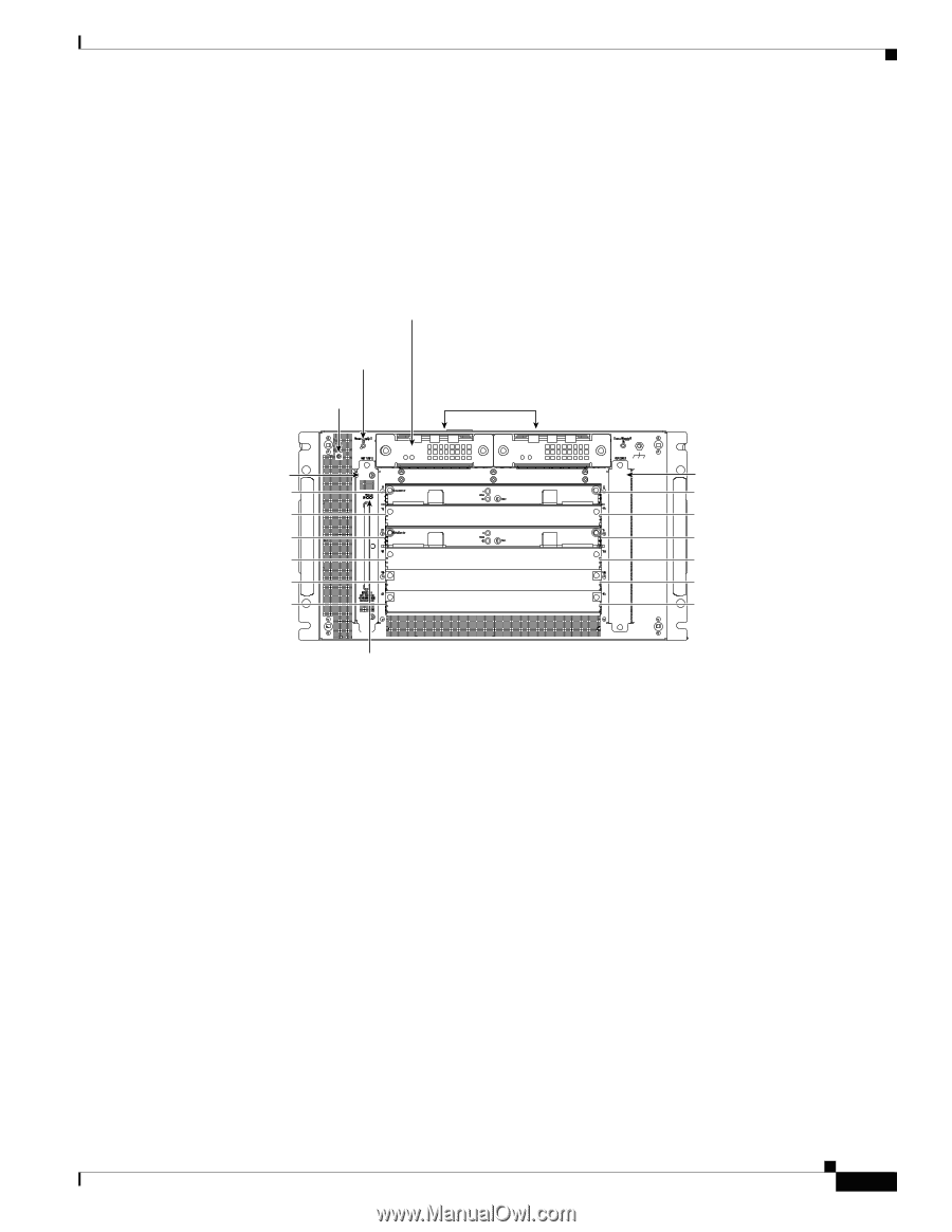
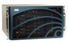
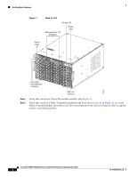
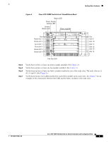
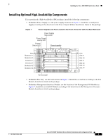
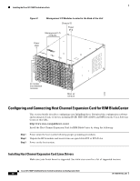
Installing the Cisco SFS 7008P Switch into a Rack Installing Optional High-Availability Components If you purchased a High-Availability (HA) package, install the following components: • Redundant Power Supply; see the power supply locations in Figure 7. Install the second power supply according to the directions in the Power Supply Module Installation Guide in the package. Figure 7 Power Supplies and Fans Located in the Front of the Unit with the Bezel Removed Power Supply Status LED Power Supply identity LED System Status LED Power supplies Fan Node slot 1 Node slot 2 Core slot 1 Core slot 2 Node slot 3 Node slot 4 Fan Slot 9 Slot 10 Slot 11 Slot 12 Slot 13 Slot 14 154497 Fan tray LED • Redundant Fan Tray; see the fan locations in Figure 7. Install the second fan according to the Fan Module Installation Guide in the package. • Redundant Management Interface Module; see the location of the Management I/O Modules in Figure 8. Install the second I/O Module according to the directions in the Management Interface Module Installation Guide in the package. 78-17434-01 Rev. A0 Cisco SFS 7008P InfiniBand Server Switch Installation and Configuration Note 9
-
 1
1 -
2
-
3
-
 4
4 -
 5
5 -
 6
6 -
 7
7 -
 8
8 -
 9
9 -
 10
10 -
 11
11 -
 12
12 -
 13
13 -
 14
14 -
15
-
16
-
17
-
18
-
19
-
20
-
21
-
22
-
23
-
24
-
25
-
26
-
27
-
28
-
29
-
30
-
31
-
32
-
33
-
34
 |
 |