Cisco AIR-RM1252G-A-K9= Hardware Installation Guide - Page 68
Checking the Power Injector LEDs
 |
UPC - 882658140860
View all Cisco AIR-RM1252G-A-K9= manuals
Add to My Manuals
Save this manual to your list of manuals |
Page 68 highlights
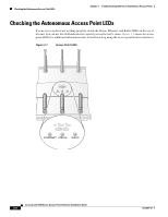
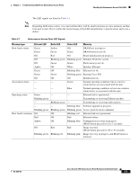
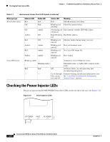
Checking the Power Injector LEDs Chapter 3 Troubleshooting 1250 Series Autonomous Access Points Table 3-1 Autonomous Access Point LED Signals (continued) Message type Boot loader errors Cisco IOS errors Ethernet LED Radio LED Status LED Meaning Red Red Red DRAM memory test failure. Off Red Blinking red Flash file system failure. and blue Off Amber Alternating red Environment variable (ENVAR) failure. and green Amber Off Rapid blinking Bad MAC address. red Red Off Blinking red Ethernet failure during image recovery. and off Amber Amber Blinking red Boot environment error. and off Red Amber Blinking red No Cisco IOS image file. and off Amber Amber Blinking red Boot failure. and off Blinking amber - - Transmit or receive Ethernet errors. - Blinking amber - Maximum retries or buffer full occurred on the radio. Red Red Off Software failure; try disconnecting and reconnecting unit power. - - Cycle through General warning, insufficient inline power (see blue, green, the "Low Power Condition on Autonomous red, and off Access Points" section). Checking the Power Injector LEDs The power injector (model:AIR-PWRINJ4) has three LEDs on the top end of the case (see Figure 3-2). Figure 3-2 Power Injector LEDs AP POWER FAULT AC POWER Cisco Aironet 1250 Series Access Point Hardware Installation Guide 3-4 170366 OL-8247-03
-
 1
1 -
2
-
3
-
4
-
5
-
6
-
7
-
8
-
9
-
10
-
11
-
12
-
13
-
14
-
15
-
16
-
17
-
18
-
19
-
20
-
21
-
22
-
23
-
24
-
25
-
26
-
27
-
28
-
29
-
30
-
31
-
32
-
33
-
34
-
35
-
36
-
37
-
38
-
39
-
40
-
41
-
42
-
43
-
44
-
45
-
46
-
47
-
48
-
49
-
50
-
51
-
52
-
53
-
54
-
55
-
56
-
57
-
58
-
59
-
60
-
61
-
62
-
 63
63 -
 64
64 -
 65
65 -
 66
66 -
 67
67 -
 68
68 -
 69
69 -
 70
70 -
 71
71 -
 72
72 -
 73
73 -
74
-
75
-
76
-
77
-
78
-
79
-
80
-
81
-
82
-
83
-
84
-
85
-
86
-
87
-
88
-
89
-
90
-
91
-
92
-
93
-
94
-
95
-
96
-
97
-
98
-
99
-
100
-
101
-
102
-
103
-
104
-
105
-
106
-
107
-
108
-
109
-
110
-
111
-
112
-
113
-
114
-
115
-
116
-
117
-
118
-
119
-
120
-
121
-
122
-
123
-
124
-
125
-
126
-
127
-
128
-
129
-
130
-
131
-
132
-
133
-
134
-
135
-
136
-
137
-
138
-
139
-
140
-
141
-
142
 |
 |
