Cisco CP-7914 Quick Start Guide - Page 10
Connect the RS 232 Cable, Step 1 - ip phone
 |
UPC - 746320615165
View all Cisco CP-7914 manuals
Add to My Manuals
Save this manual to your list of manuals |
Page 10 highlights
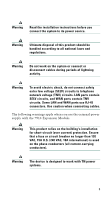
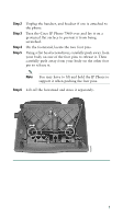
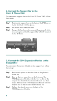
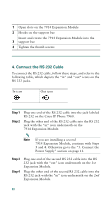
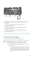
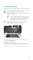
1 Open slots on the 7914 Expansion Module 2 Hooks on the support bar Insert and rotate the 7914 Expansion Module into the 3 support bar 4 Tighten the thumb screws 4. Connect the RS 232 Cable To connect the RS 232 cable, follow these steps, and refer to the following table, which depicts the "in" and "out" icons on the RS 232 jacks. In icon Out icon Step 1 Step 2 Plug one end of the RS 232 cable into the jack labeled RS 232 on the Cisco IP Phone 7960. Plug the other end of the RS 232 cable into the RS 232 jack with the "in" icon underneath on the 7914 Expansion Module. Note If you are installing a second 7914 Expansion Module, continue with Steps 3 and 4. Otherwise go to the "5. Connect the Power Supply" section on page 11. Step 3 Step 4 Plug one end of the second RS 232 cable into the RS 232 jack with the "out" icon underneath on the 1st Expansion Module. Plug the other end of the second RS 232 cable into the RS 232 jack with the "in" icon underneath on the 2nd Expansion Module. 10
-
 1
1 -
2
-
3
-
4
-
 5
5 -
 6
6 -
 7
7 -
 8
8 -
 9
9 -
 10
10 -
 11
11 -
 12
12 -
 13
13 -
 14
14 -
 15
15 -
16
-
17
-
18
-
19
-
20
-
21
-
22
-
23
-
24
-
25
-
26
-
27
-
28
 |
 |