Cisco CP-7914 Quick Start Guide - Page 11
Connect the Power Supply, Expansion Module 1 - cable
 |
UPC - 746320615165
View all Cisco CP-7914 manuals
Add to My Manuals
Save this manual to your list of manuals |
Page 11 highlights
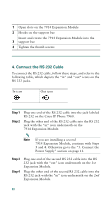
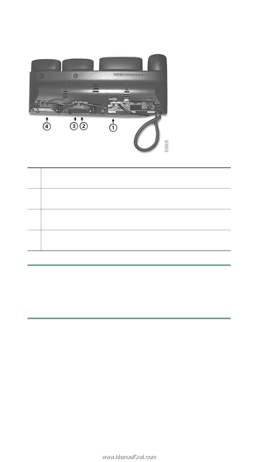
RS 232 cable connection to the RS 232 jack on the 1 IP Phone RS 232 cable connection to the RS 232 jack on 2 Expansion Module 1 2nd RS 232 cable connection to the RS 232 jack on 3 Expansion Module 1 2nd RS 232 cable connection to the RS 232 jack on 4 Expansion Module 2 5. Connect the Power Supply To connect the power supply, follow these steps. Step 1 Depending on how your Cisco IP Phone 7960 is powered, perform one of the following actions: • If your Cisco IP Phone 7960 is powered over the Ethernet and: - you have one Expansion Module-connect the power supply unit to the AC adaptor port on the Expansion Module and plug the other end into a standard electrical power outlet in the wall. 11
-
 1
1 -
2
-
3
-
4
-
5
-
 6
6 -
 7
7 -
 8
8 -
 9
9 -
 10
10 -
 11
11 -
 12
12 -
 13
13 -
 14
14 -
 15
15 -
 16
16 -
17
-
18
-
19
-
20
-
21
-
22
-
23
-
24
-
25
-
26
-
27
-
28
 |
 |
11
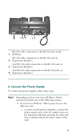
5. Connect the Power Supply
To connect the power supply, follow these steps.
Step 1
Depending on how your Cisco IP Phone 7960 is
powered, perform one of the following actions:
•
If your Cisco IP Phone 7960 is powered over the
Ethernet and:
–
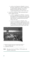
you have one Expansion Module—connect the
power supply unit to the AC adaptor port on
the Expansion Module and plug the other end
into a standard electrical power outlet in the
wall.
1
RS 232 cable connection to the RS 232 jack on the
IP Phone
2
RS 232 cable connection to the RS 232 jack on
Expansion Module 1
3
2nd RS 232 cable connection to the RS 232 jack on
Expansion Module 1
4
2nd RS 232 cable connection to the RS 232 jack on
Expansion Module 2