Cisco RV082 User Guide - Page 93
Wall-Mounting the Router, D-3: Wall-Mounting the Router
 |
UPC - 745883556700
View all Cisco RV082 manuals
Add to My Manuals
Save this manual to your list of manuals |
Page 93 highlights
10/100 8-Port VPN Router Wall-Mounting the Router The Router is shown in Figure D-3 with two holes on the bottom. The horizontal distant between the two holes is 3.701 in (94mm). Install two screws or nails into the wall, 3.701 in (94 mm) apart. After the nails are secured on the wall, line up the Router's holes with the screws on the wall to wall-mount it. The wall-mount holes are shown below, in Figure D-3. The suggested mounting hardware is shown in Figure D-4. Figure D-3: Wall-Mounting the Router Appendix D: Physical Setup of the Router 84 Setting up the Router
-
 1
1 -
2
-
3
-
4
-
5
-
6
-
7
-
8
-
9
-
10
-
11
-
12
-
13
-
14
-
15
-
16
-
17
-
18
-
19
-
20
-
21
-
22
-
23
-
24
-
25
-
26
-
27
-
28
-
29
-
30
-
31
-
32
-
33
-
34
-
35
-
36
-
37
-
38
-
39
-
40
-
41
-
42
-
43
-
44
-
45
-
46
-
47
-
48
-
49
-
50
-
51
-
52
-
53
-
54
-
55
-
56
-
57
-
58
-
59
-
60
-
61
-
62
-
63
-
64
-
65
-
66
-
67
-
68
-
69
-
70
-
71
-
72
-
73
-
74
-
75
-
76
-
77
-
78
-
79
-
80
-
81
-
82
-
83
-
84
-
85
-
86
-
87
-
 88
88 -
 89
89 -
 90
90 -
 91
91 -
 92
92 -
 93
93 -
 94
94 -
 95
95 -
 96
96 -
 97
97 -
 98
98 -
99
-
100
-
101
-
102
-
103
-
104
-
105
 |
 |

84
Appendix D: Physical Setup of the Router
Setting up the Router
10/100 8-Port VPN Router
Wall-Mounting the Router
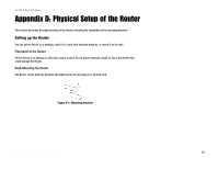
The Router is shown in Figure D-3 with two holes on the bottom. The horizontal distant between the two holes is
3.701 in (94mm). Install two screws or nails into the wall, 3.701 in (94 mm) apart. After the nails are secured on
the wall, line up the Router’s holes with the screws on the wall to wall-mount it. The wall-mount holes are shown
below, in Figure D-3. The suggested mounting hardware is shown in Figure D-4.
Figure D-3: Wall-Mounting the Router