Cisco WS-X4515 Hardware Maintenance Manual - Page 100
Memory Replacement Procedures, Network Processor Module Locations, Caution
 |
UPC - 746320659190
View all Cisco WS-X4515 manuals
Add to My Manuals
Save this manual to your list of manuals |
Page 100 highlights
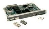
Memory Replacement Procedures Figure 5-4 Network Processor Module Locations Module handles Male module connector (cutaway view) Chassis wall H1048a Safety latch Module mounting screw Female module connector on the motherboard Memory Replacement Procedures There are two dynamic random-access memory (DRAM) systems in Cisco 4000 series routers. One is the shared memory, which is the interface that the network processor modules send data to or transmit data from, and the other is the primary or main memory, which is reserved for the CPU. In addition, the Cisco 4000-M has Flash memory for storing the system software image; the Cisco 4500-M and Cisco 4700 have Flash memory for the system software image and for the boot helper image. Caution To avoid damaging ESD-sensitive components, observe all ESD precautions. To avoid damaging the underlying system card, avoid using excessive force when you remove or replace SIMMs. The Cisco 4000-M main memory upgrade requires replacing the main memory configuration of 4 MB (one 4-MB SIMM) with one 8, 16, or 32-MB SIMM. The Cisco 4500-M main memory upgrade requires replacing the main memory configuration of 8 MB (two 4-MB SIMMs) with two 8-MB SIMMs or two 16-MB SIMMs. The Cisco 4700 main memory upgrade requires replacing the main memory configuration of 16 MB (two 8-MB SIMMs) with two 16-MB SIMMs. For the Cisco 4000-M shared memory upgrade, replace the 4-MB shared memory SIMM with a 16-MB shared memory SIMM. The Cisco 4500-M and Cisco 4700 shared memory upgrade permits you to replace the 4-MB shared memory SIMM with an 8-MB SIMM or a 16-MB SIMM. 5-6 Cisco 4000 Series Hardware Installation and Maintenance
-
 1
1 -
2
-
3
-
4
-
5
-
6
-
7
-
8
-
9
-
10
-
11
-
12
-
13
-
14
-
15
-
16
-
17
-
18
-
19
-
20
-
21
-
22
-
23
-
24
-
25
-
26
-
27
-
28
-
29
-
30
-
31
-
32
-
33
-
34
-
35
-
36
-
37
-
38
-
39
-
40
-
41
-
42
-
43
-
44
-
45
-
46
-
47
-
48
-
49
-
50
-
51
-
52
-
53
-
54
-
55
-
56
-
57
-
58
-
59
-
60
-
61
-
62
-
63
-
64
-
65
-
66
-
67
-
68
-
69
-
70
-
71
-
72
-
73
-
74
-
75
-
76
-
77
-
78
-
79
-
80
-
81
-
82
-
83
-
84
-
85
-
86
-
87
-
88
-
89
-
90
-
91
-
92
-
93
-
94
-
 95
95 -
 96
96 -
 97
97 -
 98
98 -
 99
99 -
 100
100 -
 101
101 -
 102
102 -
 103
103 -
 104
104 -
 105
105 -
106
-
107
-
108
-
109
-
110
-
111
-
112
-
113
-
114
-
115
-
116
-
117
-
118
-
119
-
120
-
121
-
122
-
123
-
124
-
125
-
126
-
127
-
128
-
129
-
130
-
131
-
132
-
133
-
134
-
135
-
136
-
137
-
138
-
139
-
140
-
141
-
142
-
143
 |
 |
