Cisco WS-X4515 Hardware Maintenance Manual - Page 57
ATM Cabling
 |
UPC - 746320659190
View all Cisco WS-X4515 manuals
Add to My Manuals
Save this manual to your list of manuals |
Page 57 highlights
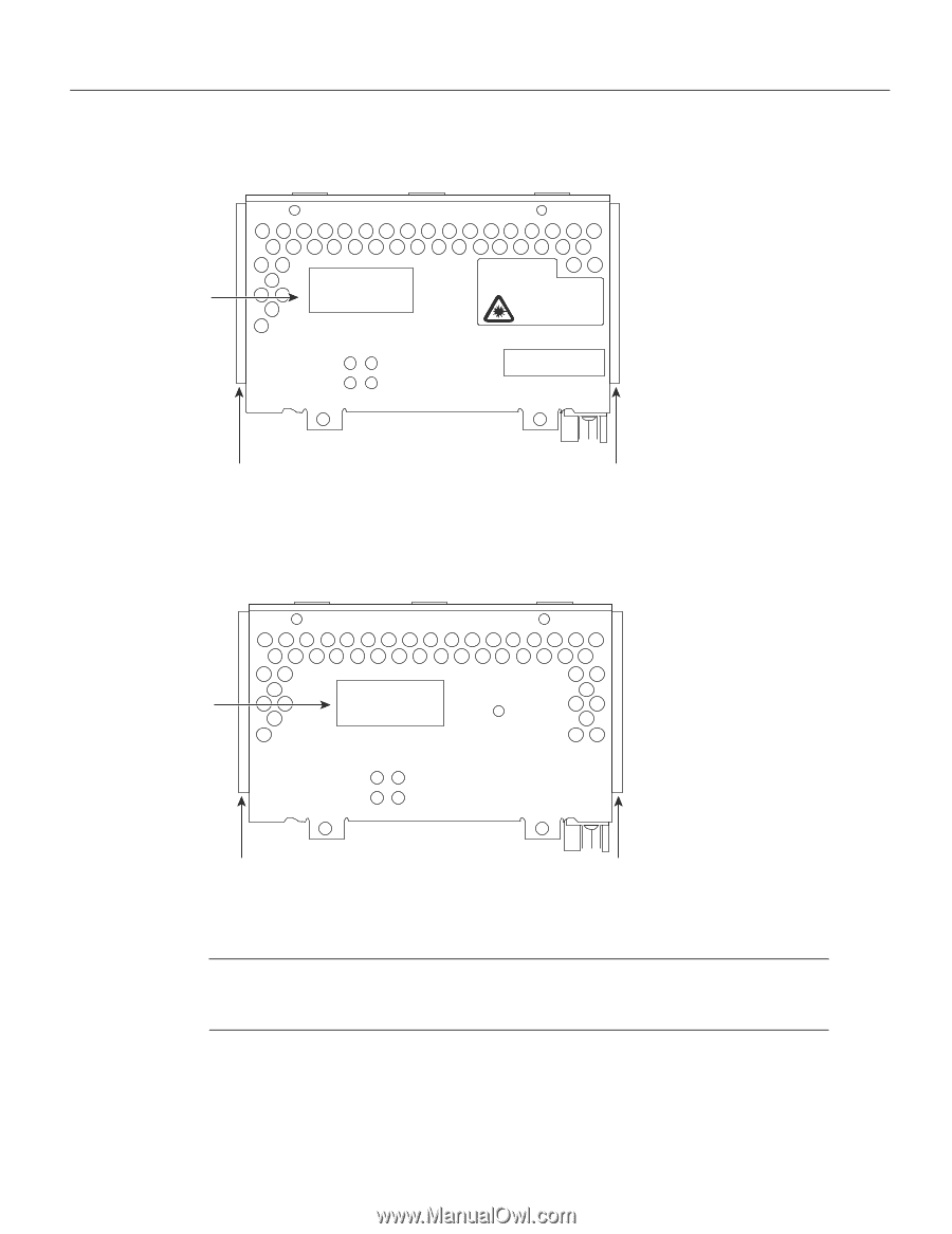
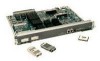
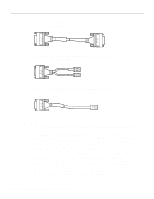
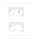
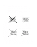
Network Connection Considerations Figure 2-40 ATM Network Processor Module with STS-3c/STM-1 Single Mode PLIM ector XMTR BUSY READY ATM SM RCVR RX CELLS RX ALARM WARNING AVOID EXPOSUREÐINVISIBLE LASER RADIATION IS EMITTED FROM THESE APERTURES. 1300 NM CLASS 1 LASER PRODUCT LASERKLASSE 1 CISCO SYSTEMS, INC. 170 W. TASMAN DRIVE SAN JOSE CA. 95134 DATE: ÒComplies with FDA Radiation Performance Standards, 21 CFR, Subchapter JÓ H3157 Alignment groove Alignment groove Figure 2-41 ATM Network Processor Module with STS-3c/STM-1 Multimode PLIM ector Alignment groove XMTR BUSY READY ATM MM RCVR RX CELLS RX ALARM Alignment groove H3156 Note Traffic from multiple ATM interfaces could exceed the available bandwidth in the router, causing packets to be dropped. Therefore the Cisco 4500-M and Cisco 4700 routers currently support one ATM module. ATM Cabling For single- or multi-mode SONET connections, connect the fiber cable to the SC-style receptacle on the module front panel. The SONET SC-duplex connector is shipped with a dust plug. Remove the plug by pulling on the plug as you squeeze the sides of the connector. Preparing for Installation 2-35
-
 1
1 -
2
-
3
-
4
-
5
-
6
-
7
-
8
-
9
-
10
-
11
-
12
-
13
-
14
-
15
-
16
-
17
-
18
-
19
-
20
-
21
-
22
-
23
-
24
-
25
-
26
-
27
-
28
-
29
-
30
-
31
-
32
-
33
-
34
-
35
-
36
-
37
-
38
-
39
-
40
-
41
-
42
-
43
-
44
-
45
-
46
-
47
-
48
-
49
-
50
-
51
-
 52
52 -
 53
53 -
 54
54 -
 55
55 -
 56
56 -
 57
57 -
 58
58 -
 59
59 -
 60
60 -
 61
61 -
 62
62 -
63
-
64
-
65
-
66
-
67
-
68
-
69
-
70
-
71
-
72
-
73
-
74
-
75
-
76
-
77
-
78
-
79
-
80
-
81
-
82
-
83
-
84
-
85
-
86
-
87
-
88
-
89
-
90
-
91
-
92
-
93
-
94
-
95
-
96
-
97
-
98
-
99
-
100
-
101
-
102
-
103
-
104
-
105
-
106
-
107
-
108
-
109
-
110
-
111
-
112
-
113
-
114
-
115
-
116
-
117
-
118
-
119
-
120
-
121
-
122
-
123
-
124
-
125
-
126
-
127
-
128
-
129
-
130
-
131
-
132
-
133
-
134
-
135
-
136
-
137
-
138
-
139
-
140
-
141
-
142
-
143
 |
 |