Cisco WS-X4515 Hardware Maintenance Manual - Page 102
Replacing Main Memory SIMMs, Memory Replacement Procedures,
 |
UPC - 746320659190
View all Cisco WS-X4515 manuals
Add to My Manuals
Save this manual to your list of manuals |
Page 102 highlights
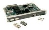
Memory Replacement Procedures Figure 5-6 shows the Cisco 4500-M and Cisco 4700 SIMM and jumper locations. Figure 5-6 Cisco 4500-M and Cisco 4700 SIMM Locations Shared-memory SIMM and socket Motherboard Main memory SIMM sockets with correct SIMM orientation Front of chassis NVRAM Jumped pins 1 and 2 J6 J1 U68 Jumper in place enables writing to Flash memory ROM monitor H2449 System Flash memory 1 System Flash memory 0 RxBoot Flash memory Replacing Main Memory SIMMs SIMMs are manufactured with a polarization notch to prevent them from being installed backward. Figure 5-7 shows the polarization notch and locations of the alignment holes on a main memory SIMM card. The main memory SIMM cards are installed with the connector edge down and the component side facing in, as shown in the upper right of Figure 5-5 and Figure 5-6. Figure 5-7 Cisco 4000 Series Main Memory SIMM Alignment holes H2407 Connector edge 5-8 Cisco 4000 Series Hardware Installation and Maintenance Polarization notch
-
 1
1 -
2
-
3
-
4
-
5
-
6
-
7
-
8
-
9
-
10
-
11
-
12
-
13
-
14
-
15
-
16
-
17
-
18
-
19
-
20
-
21
-
22
-
23
-
24
-
25
-
26
-
27
-
28
-
29
-
30
-
31
-
32
-
33
-
34
-
35
-
36
-
37
-
38
-
39
-
40
-
41
-
42
-
43
-
44
-
45
-
46
-
47
-
48
-
49
-
50
-
51
-
52
-
53
-
54
-
55
-
56
-
57
-
58
-
59
-
60
-
61
-
62
-
63
-
64
-
65
-
66
-
67
-
68
-
69
-
70
-
71
-
72
-
73
-
74
-
75
-
76
-
77
-
78
-
79
-
80
-
81
-
82
-
83
-
84
-
85
-
86
-
87
-
88
-
89
-
90
-
91
-
92
-
93
-
94
-
95
-
96
-
 97
97 -
 98
98 -
 99
99 -
 100
100 -
 101
101 -
 102
102 -
 103
103 -
 104
104 -
 105
105 -
 106
106 -
 107
107 -
108
-
109
-
110
-
111
-
112
-
113
-
114
-
115
-
116
-
117
-
118
-
119
-
120
-
121
-
122
-
123
-
124
-
125
-
126
-
127
-
128
-
129
-
130
-
131
-
132
-
133
-
134
-
135
-
136
-
137
-
138
-
139
-
140
-
141
-
142
-
143
 |
 |
