Cisco WS-X4515 Hardware Maintenance Manual - Page 69
Making FDDI Network Connections, Host Power Supply Requirements, Additional Safety Information
 |
UPC - 746320659190
View all Cisco WS-X4515 manuals
Add to My Manuals
Save this manual to your list of manuals |
Page 69 highlights
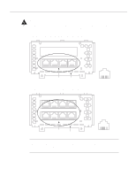
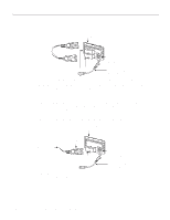
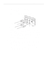
Making Network Connections Host Power Supply Requirements The power requirements of the BRI network processor module are as follows: • +5 VDC/2.5 mA • +12 VDC/100 mA • -12 VDC/100 mA Ensure that the power drawn by the apparatus, together with the power drawn by any auxiliary apparatus, lies within the rating of the host chassis power supply. Additional Safety Information The BRI network processor modules contain safety extra-low voltage (SELV) circuitry. Ensure that attachments at the interconnection ports of the apparatus are also SELV circuits. (SELV circuits are so designed and protected that, under both normal conditions and a likely fault condition, the current which can be drawn is not hazardous). Always disconnect the host chassis from the power supply before removing any covers. Always disconnect the host chassis from any analog telephone circuits or Basic Access ISDN (where applicable) before removing any covers. Failure to install the BRI modules in accordance with these instructions will invalidate any telecommunication terminal equipment type approval(s). If you have any doubt as to how to safely install the Cisco Systems BRI module correctly within a host chassis, seek advice from a qualified telecommunications engineer. Making FDDI Network Connections Follow these procedures to make Fiber Distributed Data Interface (FDDI) connections. Dual-Attachment FDDI Connections Connect a dual-attachment FDDI module as follows: Step 1 To connect to a dual-attachment station (DAS), connect PHY-A on the FDDI module (the bottom port) to PHY-B on the other DAS using a multimode fiber-optic cable. (See Figure 3-10.) Installing the Router 3-11
-
 1
1 -
2
-
3
-
4
-
5
-
6
-
7
-
8
-
9
-
10
-
11
-
12
-
13
-
14
-
15
-
16
-
17
-
18
-
19
-
20
-
21
-
22
-
23
-
24
-
25
-
26
-
27
-
28
-
29
-
30
-
31
-
32
-
33
-
34
-
35
-
36
-
37
-
38
-
39
-
40
-
41
-
42
-
43
-
44
-
45
-
46
-
47
-
48
-
49
-
50
-
51
-
52
-
53
-
54
-
55
-
56
-
57
-
58
-
59
-
60
-
61
-
62
-
63
-
 64
64 -
 65
65 -
 66
66 -
 67
67 -
 68
68 -
 69
69 -
 70
70 -
 71
71 -
 72
72 -
 73
73 -
 74
74 -
75
-
76
-
77
-
78
-
79
-
80
-
81
-
82
-
83
-
84
-
85
-
86
-
87
-
88
-
89
-
90
-
91
-
92
-
93
-
94
-
95
-
96
-
97
-
98
-
99
-
100
-
101
-
102
-
103
-
104
-
105
-
106
-
107
-
108
-
109
-
110
-
111
-
112
-
113
-
114
-
115
-
116
-
117
-
118
-
119
-
120
-
121
-
122
-
123
-
124
-
125
-
126
-
127
-
128
-
129
-
130
-
131
-
132
-
133
-
134
-
135
-
136
-
137
-
138
-
139
-
140
-
141
-
142
-
143
 |
 |
